Object line acquisition device and terminal equipment

A technology of collection device and terminal equipment, applied in instruments, character and pattern recognition, computer parts and other directions, can solve the problem of inflexible relative position setting of light source and light-emitting area, and achieve the best equipment appearance, flexible setting and compact structure. Effect

Pending Publication Date: 2021-10-29
HUAWEI TECH CO LTD
View PDF0 Cites 0 Cited by
  • Summary
  • Abstract
  • Description
  • Claims
  • Application Information

AI Technical Summary

Problems solved by technology

[0004] One object of the present application is to provide a collection device for textures of objects, aiming at solving the problem of inflexible setting of the relative positions of the light source and the light-emitting area in the texture recognition imaging device using active light sources in the prior art

Method used


Image

  • Object line acquisition device and terminal equipment
  • Object line acquisition device and terminal equipment
  • Object line acquisition device and terminal equipment

Examples


Embodiment Construction

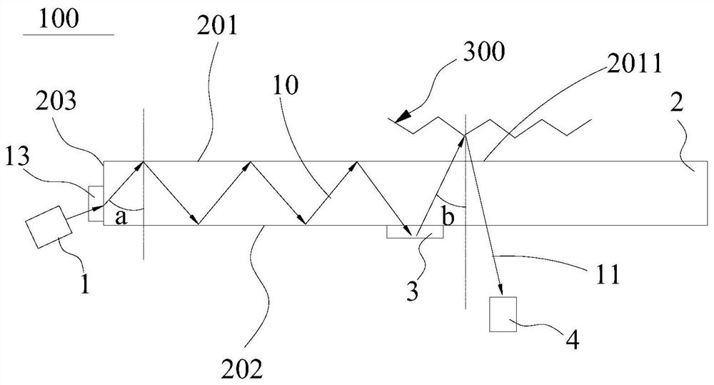
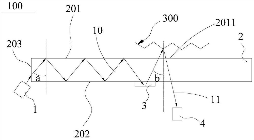
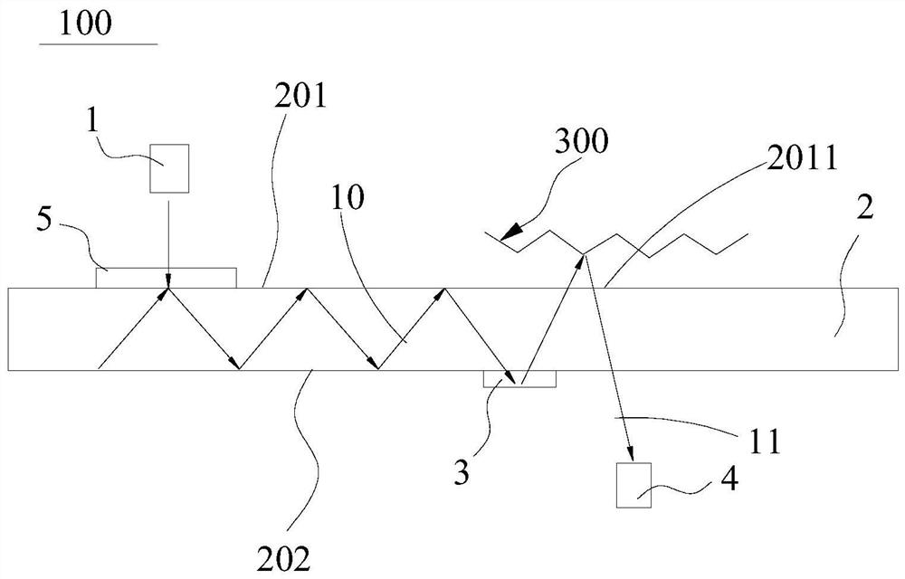
[0058] In order to make the purpose, technical solution and advantages of the present application clearer, the present application will be further described in detail below in conjunction with the accompanying drawings and embodiments. It should be understood that the specific embodiments described here are only used to explain the present application, and are not intended to limit the present application.

[0059] It should be noted that when an element is referred to as being “fixed” or “disposed on” another element, it may be directly on the other element or be indirectly on the other element. When an element is referred to as being "connected to" another element, it can be directly connected to the other element or indirectly connected to the other element.

[0060] It is to be understood that the terms "length", "width", "top", "bottom", "front", "rear", "left", "right", "vertical", "horizontal", "top" , "bottom", "inner", "outer" and other indicated orientations or posi...


PUM

PropertyMeasurementUnit
Thicknessaaaaaaaaaa

Abstract

The invention discloses an object line acquisition device and terminal equipment, and relates to the field of line recognition. The object line acquisition device comprises a light source, a light guide plate, a first coupler and an image sensor, wherein the light source is used for emitting detection light; the light guide plate is used for transmitting the detection light to the first coupler in a total reflection mode, and the light guide plate is provided with a light emitting area; the first coupler is arranged close to the light guide surface of the light guide plate, and is used for releasing the total reflection state of the detection light in the light guide plate when receiving the detection light, and guiding the detection light to the light emitting area, so that the detection light leaves the light guide plate from the light emitting area and is transmitted to an object to be identified. The image sensor is used for receiving detection light formed after the object to be identified reflects the detection light. The light guide plate transmits light emitted by the light source in the total reflection mode, then the light is guided to the light emitting area through diffraction deflection of the first coupler, and the light leaves the light guide plate and reaches the object to be identified, and the light source does not need to be arranged near the light emitting area.

Description

technical field [0001] The present application relates to the field of object texture recognition, in particular to an object texture collection device and terminal equipment. Background technique [0002] The imaging recognition technology of optical fingerprints and palmprints and other lines uses optical sensors to collect line images and compare them with the existing line imaging information in the system to make judgments. [0003] In the related art, the texture recognition imaging device using active light source illumination has better imaging quality and high accuracy of texture collection during use. However, in the above-mentioned texture recognition imaging device using an active light source, the light source needs to be configured closer to the light-emitting area, and the light source and the light-emitting area need to meet a specific relative positional relationship to build an optical path for collecting patterns, that is, the relative position of the ligh...

Claims


Application Information

Patent Timeline
IPC IPC(8): G06K9/00G06K9/20
Inventor 王恒胡晓阳叶海水
Owner HUAWEI TECH CO LTD
Why Eureka
Try Eureka