Image compressing apparatus, image compressing method and vehicle-mounted image recording apparatus

a compression apparatus and compression method technology, applied in the field of image compression apparatus and image compression method, can solve the problems of increasing the amount of coding and the difficulty of recording images, and achieve the effects of improving image quality, reducing data compression rate, and high likelihood

Inactive Publication Date: 2011-11-03
PANASONIC CORP
View PDF2 Cites 35 Cited by
  • Summary
  • Abstract
  • Description
  • Claims
  • Application Information

AI Technical Summary

Benefits of technology

[0083]According to the present invention, the display screen of the surrounding image data is divided into a plurality of divided regions based on the shape of the road where the vehicle is currently running, and the surrounding image data in any of the divided regions where there is a high likelihood of accident is compressed with a lower data compression rate to place an emphasis on improvement of an image quality, and the surrounding image data in any other regions is compressed with a higher data compression rate so that the compression coding amount is reduced. This technical characteristic enables the image data to be recorded over a long period of time while ensuring a high image quality in any images of significance, thereby dissolving the relationship of trade-off between the image quality and recording time.
[0084]Another technical advantage to be emphasized is to record images with an image quality flexibly set for different circumstances by controlling the image data compression rate and / or frame rate based on the positional information, speed information, and acceleration information of the vehicle.

Problems solved by technology

When the image data compression rate is lowered to improve the image quality, however, a compression coding amount increases, making it difficult to record the images over a long period of time.

Method used


Image

  • Image compressing apparatus, image compressing method and vehicle-mounted image recording apparatus
  • Image compressing apparatus, image compressing method and vehicle-mounted image recording apparatus
  • Image compressing apparatus, image compressing method and vehicle-mounted image recording apparatus

Examples


exemplary embodiment 1

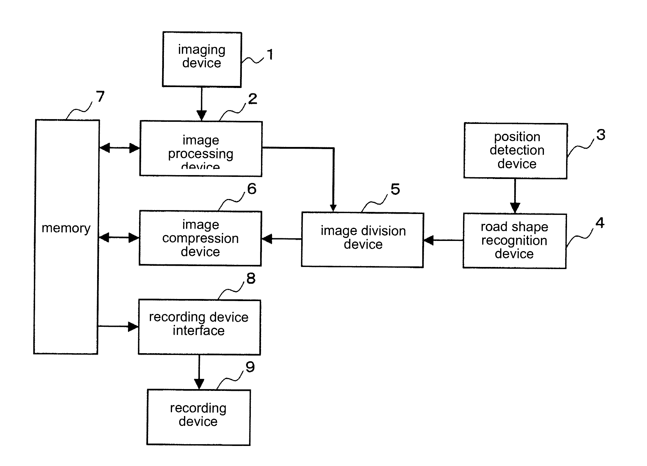
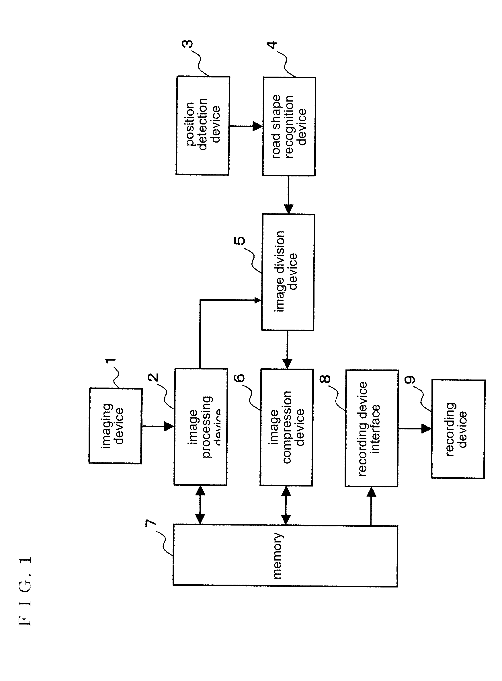
[0129]FIG. 1 is a block diagram illustrating a structural characteristic of a vehicle-mounted image recording apparatus according to an exemplary embodiment 1 of the present invention.

[0130]The vehicle-mounted image recording apparatus has an imaging device 1, an image processing device 2, a position detection device 3, a road shape recognition device 4, an image division device 5, an image compression device 6, a memory 7, a recording device interface 8, and a recording device 9.

[0131]The imaging device 1 captures surrounding images of a currently travelling vehicle loaded with the apparatus. The image processing device 2 image-processes data of the surrounding images outputted from the imaging device 1. The position detection device 3 detects a position of the currently travelling vehicle. The road shape recognition device 4 stores therein map information including road shapes at different locations in advance, and checks the vehicle position detected by the position detection dev...

exemplary embodiment 2

[0161]FIG. 17 is a block diagram illustrating a structural characteristic of a vehicle-mounted image recording apparatus according to an exemplary embodiment 2 of the present invention. The same reference symbols illustrated in FIG. 17 as those of FIG. 1 according to the exemplary embodiment 1 denote the same structural elements. The present exemplary embodiment is technically characterized in that a vehicle speed detection device 10 configured to detect the travelling speed of the vehicle is further provided in the structure according to the exemplary embodiment 1. The image division device 5 is configured to divide the surrounding image data based on the recognition result of the road shape recognition device 4 and a detection result of the vehicle speed detection device 10 and differently allocate the data compression rate suitable for each of the divided regions. The travelling speed of the vehicle detected by the vehicle speed detection device 10 is transmitted to the image div...

exemplary embodiment 3

[0163]The rate of accident occurrence is associated with the driving conditions of the vehicle as well as the road shape. An exemplary embodiment 3 of the present invention focuses on a travelling speed of the vehicle among the driving conditions of the vehicle. An accident is less likely to occur when the vehicle is driven really slow but is more likely to occur when the vehicle increases its speed to run faster. Therefore, the surrounding image data is preferably recorded with a high image quality when the vehicle is travelling at a high speed.

[0164]FIG. 20 is a block diagram illustrating a structural characteristic of a vehicle-mounted image recording apparatus according to the exemplary embodiment 3. The vehicle-mounted image recording apparatus has an imaging device 1 configured to capture surrounding images of the vehicle, an image processing device 2 configured to image-process data of the surrounding images outputted from the imaging device 1, a vehicle speed detection devic...


PUM


Abstract

A road shape recognition device checks a position of a currently travelling vehicle detected by a position detection device with map information so that a road shape at each travelling spot of the currently travelling vehicle is recognized. An image division device divides a display screen of surrounding image data of the currently travelling vehicle into a plurality of divided regions depending on the road shape and sets a data compression rate suitable for the road shape in each of the plurality of divided regions. An image compression device compresses the surrounding image data in each of the plurality of divided regions into codes based on the data compression rate set for each of the divided regions.

Description

FIELD OF THE INVENTION[0001]The present invention relates to, an image compressing apparatus and an image compressing method developed for a vehicle-mounted camera, and a vehicle-mounted image recording apparatus, more particularly to a technology for dissolving the relationship of trade-off between an image quality and recording time by adaptively controlling a data compression rate and a frame rate applied to an image depending on road conditions and driving conditions.BACKGROUND OF THE INVENTION[0002]Drive recorders mounted in vehicles available in recent years can record images of a traffic accident including images at the moment of impact and before and after the accident. A drive recorder of this type temporarily record of information of images photographed by a CCD camera and then compressed and data collected from sensors such as an acceleration sensor in a random access memory in an up-to-the-minute manner. As soon as an impact sensor is put into action in response to the o...

Claims


Application Information

Patent Timeline
Patent Type & Authority Applications(United States)
IPC IPC(8): G06K9/00H04N7/18B62D41/00G07C5/00H04N5/765H04N19/00H04N19/115H04N19/132H04N19/134H04N19/167H04N19/172H04N19/174H04N19/189H04N19/20
CPCG06K9/00798H04N5/772H04N9/8042H04N9/8205H04N19/587H04N19/115H04N19/132H04N19/17H04N19/172G06V20/588
Inventor NOTSU, TAKUMAOGAWA, MASAHIRO
Owner PANASONIC CORP
Why Eureka
Try Eureka