
Fuel cell and electric pile structure thereof

A technology of fuel cells and electric stacks, which is applied in the direction of fuel cells, circuits, electrical components, etc., can solve the problems of inability to ensure the sealing of the shell, complex internal structure, increase production costs, etc., to reduce the risk of electric stack leakage, Reduce production cost and improve sealing effect

Pending Publication Date: 2021-10-29
FTXT ENERGY TECH CO LTD
View PDF3 Cites 1 Cited by
  • Summary
  • Abstract
  • Description
  • Claims
  • Application Information

AI Technical Summary

Problems solved by technology

When the core is in operation, the internal pressure will change due to thermal expansion and contraction. In related technologies, some structures adopt the structure of adding disc springs and floating plates in the shell to overcome the dimensional changes caused by pressure, which makes the internal structure complex and increases production costs. ; Some fix the core and the shell by inserting positioning pins from the outside of the shell inward, but the sealing in the shell cannot be guaranteed, which increases the risk of stack leakage

Method used


Image

  • Fuel cell and electric pile structure thereof
  • Fuel cell and electric pile structure thereof
  • Fuel cell and electric pile structure thereof

Examples


Embodiment Construction

[0031] It should be noted that, in the case of no conflict, the embodiments of the present invention and the features in the embodiments can be combined with each other.

[0032] The following will refer to Figure 1-Figure 7 The present invention will be described in detail in combination with examples.

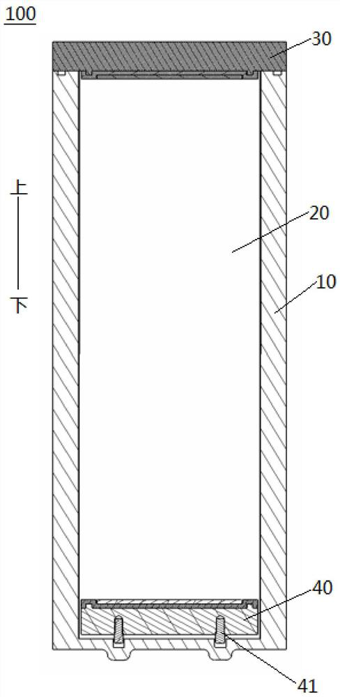
[0033] like figure 1 As shown, the fuel cell stack structure 100 according to the embodiment of the first aspect of the present invention includes: a casing 10 , a stack core 20 , a first end plate 30 and a second end plate 40 .

[0034] Specifically, the casing 10 defines an accommodating cavity 11 with an open upper end, the core 20 is disposed in the accommodating cavity 11, the first end plate 30 is disposed on the upper end of the core 20, and the second end plate 40 is disposed on the top of the core 20. lower end. That is, the first end plate 30 and the second end plate 40 are suitable for being arranged at the upper and lower ends of the core 20 .

[0035] Furthe...


PUM


Abstract

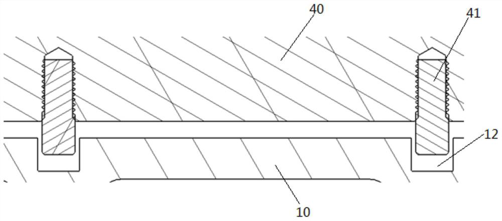
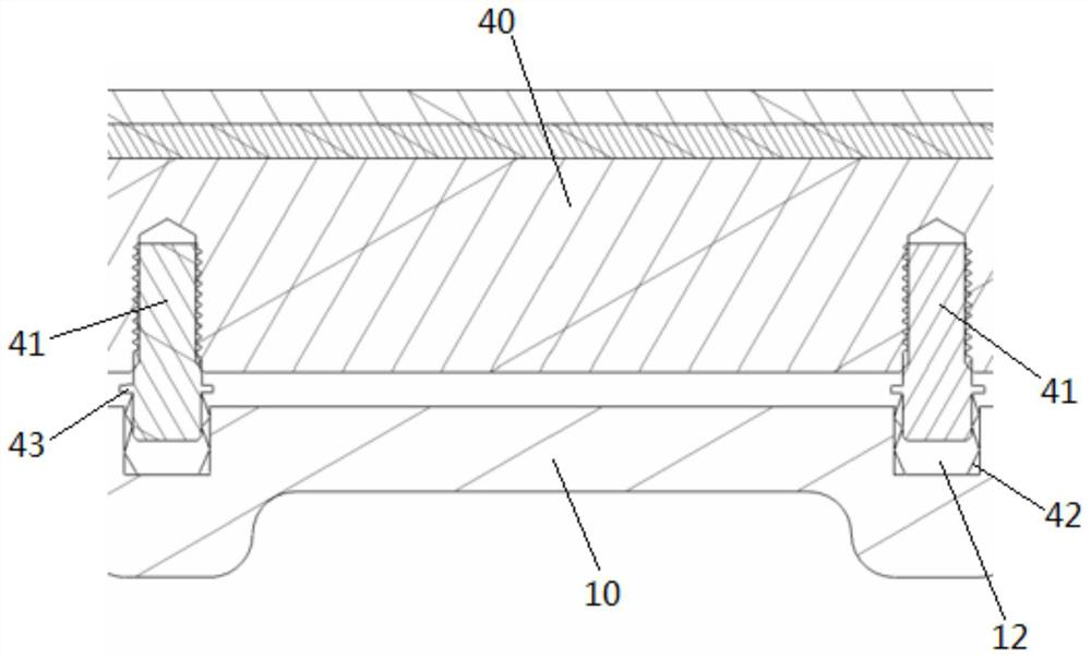
The invention discloses a fuel cell and a galvanic pile structure thereof. The galvanic pile structure comprises a housing in which an accommodating cavity with an open upper end is defined; a reactor core which is arranged in the accommodating cavity; a first end plate and a second end plate, wherein the first end plate is arranged at the upper end of the reactor core, the second end plate is arranged at the lower end of the reactor core, a positioning piece is mounted on one side, facing the inner bottom surface of the shell, of the second end plate, a positioning blind hole is formed in the inner bottom surface of the shell, the positioning piece can be matched in the positioning blind hole, and the positioning piece and the positioning blind hole are arranged at an interval in the vertical direction. According to the electric pile structure of the fuel cell, the structure is greatly simplified, the production cost is reduced, the sealing performance of the electric pile structure is improved, and the risk of electric pile leakage is reduced.

Description

technical field [0001] The present invention relates to the field of battery technology, in particular to a fuel cell and its stack structure Background technique [0002] Fuel cells are widely used in real life. Out of the need to protect the main body of the fuel cell, that is, the core, a corresponding casing is designed outside the core according to the performance and safety requirements of the stack. During the operation of the core, the internal pressure will change due to thermal expansion and contraction. In related technologies, some structures adopt the structure of adding disc springs and floating plates in the shell to overcome the dimensional changes caused by pressure, which makes the internal structure complex and increases production costs. ; Some fix the core and the shell by adding positioning pins inserted inward from the outside of the shell, but the sealing in the shell cannot be guaranteed, which increases the risk of stack leakage. Thereby, above-men...

Claims


Application Information

Patent Timeline
Patent Type & Authority Applications(China)
IPC IPC(8): H01M8/2465H01M8/2475H01M8/247
CPCH01M8/2465H01M8/2475H01M8/247Y02E60/50Y02P70/50
Inventor 王鹏杨东胜魏礼良
Owner FTXT ENERGY TECH CO LTD
Learn More