Container with removable base assembly

A container and base technology, which is applied in the container field of base components, can solve the problems of inability to clean the container, fall off of the protective pad, inconvenience for users, etc., and achieve the effect of thorough cleaning and elimination of toxic substances

Pending Publication Date: 2021-11-02
ZHEJIANG HENGFENG TOP LEISURE CO LTD
0 Cites 0 Cited by

AI-Extracted Technical Summary

Problems solved by technology

[0002] Commonly found in conventional containers with an adherent bottom pad, typically cannot be washed in hot water or on the hot dry cycle of the dishwasher a...

Abstract

The present application relates to a container with a removable base assembly having a removable base assembly. The base assembly has a resilient portion. The base assembly is removably attachable to the container in a recess of the container. The base assembly is dimensioned to stationary fit with the recess such that when the base assembly is assembled with the container, the resilient portion is exposed from the recess allowing the container to be supported on the support surface by the resilient portion of the base assembly.

Application Domain

BottlesSupporting means +3

Technology Topic

Classical mechanicsSupport surface

Image

  • Container with removable base assembly
  • Container with removable base assembly
  • Container with removable base assembly

Examples

  • Experimental program(1)

Example Embodiment

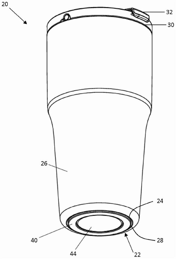
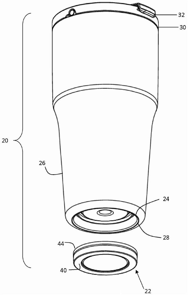
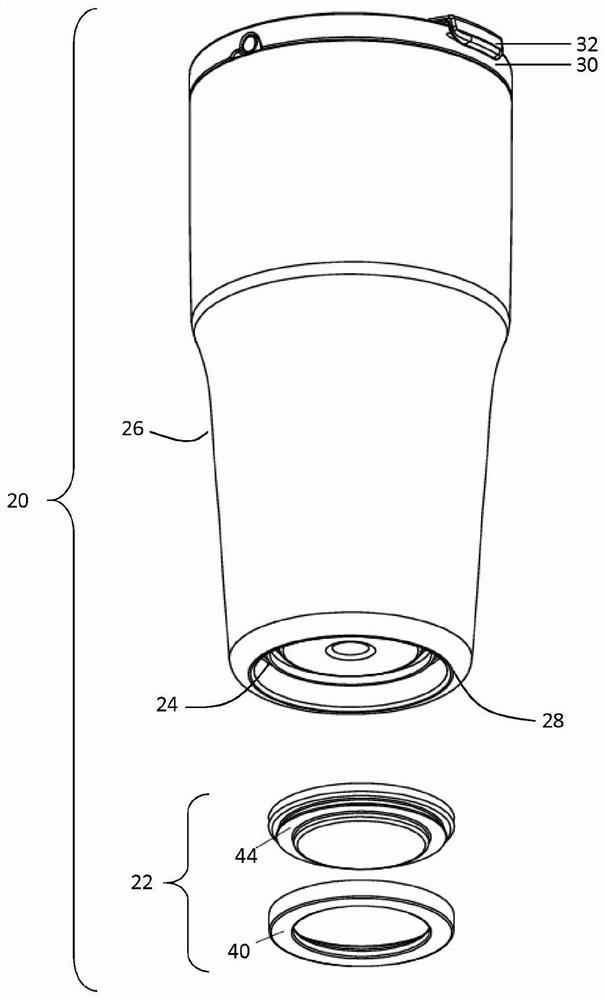
[0038] figure 1 An exemplary container 20 and the base assembly 22 in the recess 24 inserted into the container are shown. The container 20 can be a beverage container, or another individual for receiving fluid or solids using a container, wherein the container is required to vibrate and is provided on a surface that is in contact with the support surface of the container. Cushion made of materials. In the exemplary container shown in the drawings, the container 20 has a side wall 26 that defines the volume of the container and a bottom 28 extending under the side wall when the container is upright. The container can be provided with a bending transition from the side wall 26 to the bottom portion 28. The recess 24 receiving the base assembly 22 can be formed in the bottom 28. The container depicted also has a top portion 30 opposite to the bottom, and the top has an opening of the inner portion of the container, for example, for accommodating the user's beverage. The container 20 can have a removable cover 32 that covers the top opening. It should be understood that the container can have other shapes. For example, the container can be formed to be similar to a high vessel, wherein the side walls do not extend to the bottom of the container, but extend from the top to the rod, and the rod extends from the side wall to the bottom. In this configuration, the base assembly described herein can be inserted into the recess at the bottom.
[0039] The base assembly 22 can have an elastic portion 40. The elastic portion can include a cushion, and can be made of a non-slip type material. The elastic portion 40 can be made of a surface that is sufficient to provide vibration isolation, noise reduction, anti-skid / anti-slip function and can prevent sweat, anti-sweating, anti-condensation, waterproof, friction and anti-stripping surfaces shelved. Material formation. For example, the elastic portion 40 of the base assembly 22 can prevent sliding and watermarks on the desktop or furniture. As will be apparent from the above discussion, the elastic portion 40 can be formed of a compressible and elastically deformable material. If the elastic portion is blurred, the elastic portion 40 can be cleaned with a mild detergent, such as a dish soap or in a dishwasher. The elastic portion 40 can be formed from a material that can be cleaned by medium heat such as hot water such as hot water, a dry circulation or hot beverage in dishwasher. By means of example and without the meaning of any limiting, the elastic portion of the base assembly may be formed of silicone, rubber, polyurethane or polyethylene.
[0040] The base component 22 can be attached to the container 20 in a removable manner in the recess 24 of the container. Therefore, the base assembly 22 can be fixed to the recess 24 mechanical transition cooperation. The mechanical fit can be a fixed fit in which a small gap or a small interference fit between the base assembly and the recess is to allow the base assembly to assemble or disassemble or disassemble the base assembly through a light pressing force to the recess. Mechanical fit can be similar in combination, wherein the base assembly and the recess are present between minute gaps or small interference fit to allow the base assembly to be assembled or disassembled by assembling or disassembling the recess than the recess ratio in the case where the fixation is mixed. The mechanical fit may be a position fit, wherein the base assembly is a small gap between the base assembly and the recess to allow the base assembly to assemble or disassemble the concave portion by fitting or press fitting with the recess. As shown in the drawings, the recess 24 is circular and has a cylindrical hole. It should be understood that the recess 24 may have other shapes and / or may have a tapered hole. Correspondingly, the base assembly 22 is configured to provide a desired mechanical fit with the recess 24 in a similar manner.
[0041]By the concave portion 24 and the base 22 is formed as a mechanical fit assembly, the base assembly can be removably inserted into the recess. Base assembly 22 may be removed from the container 20, to allow the base assembly and container cleaning. This provides advantages over conventional containers that adhere to the protective pad or glue to the bottom of the container. In conventional containers having adherent bottom pads, due to temperature and water, the adhesive or glue is degraded and caused from being detached from the container,, for example, in hot water or in the hot dry circulation of the dishwasher. Cleaning the container. An exemplary container having a base assembly can be removably attached 22 eliminates the glue or adhesive 20, thereby eliminating potential toxic substances. It also allows the user the opportunity to purge vessel 20 and separated from each other in a base assembly 22 having a hot water or hot dishwasher cycle, thereby ensuring a more thorough cleaning. The concave portion may be provided with a peripheral edge thereof adjacent the elongated slot (not shown). Grooves may be sized to receive a coin, a key or a small tool to allow a user to pry the base assembly to be detached from the recess.
[0042] As illustrated in the drawings, the base assembly 22 comprises a carrier member 44, and the elastic portion 40 can be removably connected to the carrier member. The carrier 44 may be formed of a harder and more durable material in order to support a more flexible, resilient portion 40, and the elastic portion can be fit by a mechanical engagement with the recessed portion, as will be described below. By way of example, the carrier 44 may be formed of plastic or metal such as aluminum or stainless steel or the like. The carrier 44 may have an outer periphery, the outer periphery is shaped and dimensioned to be received in the region of the recess 24 or the recess of the container, the base assembly 22 to permit mechanical cooperation with the recessed portion. Additionally or alternatively, the resilient portion 40 may have an outer periphery, the outer periphery is shaped and dimensioned to be received in the region of the recess portion 24 or container recess, to allow the base assembly 22 with the recessed portion mechanical fit. In one example, the carrier 44 may set a region of mechanical mating shaped and dimensioned recess, and the resilient portion 40 may be given a shape and another region of the recessed portion sized to fit the machine. Elastic portion 40 and the carrier 44 with the degree of mechanical mating of the corresponding region of the recesses may be different or the same. In another example, the carrier may be given a shape and area of ​​the mechanical sized to fit the recess, and the resilient portion may be given a shape and another region of a gap sized to the recessed portion. In another example, the carrier may be a given region there is a gap shaped and dimensioned recess, and the resilient portion may be given a shape and another region of the recessed portion sized to fit the machine. Considering the characteristics of a flexible and compressible resilient portion, the resilient portion may also be interference fit with a portion of the recess or recesses. As shown in the drawings (e.g., see, Figure 7 ), The carrier member 44 can engage the first region of the recess 24, and the elastic portion 40 may engage a second region of the recess portion. Considering the carrier member 44 and the resilient portion 40 of the configuration, the elastic engagement portions 24 adjacent the recessed portion in the second region of the opening of the recess, and carries a first vertical member above the engagement opening portion and farther away from the recess in the second region a zone.
[0043] Refer Figure 4 with Figure 9 46, for example, engaging concave portions or the recessed region, the carrier member 44 may have a positioning surface 24 on the outer periphery. Carrier member 44 through the groove 50 may also have a positioning surface 46 axially spaced annular edge 48. The carrier 44 may also have annular edge 48 axially spaced annular surface 52. Positioning an outer diameter surface 46 may be larger than the outer diameter 48 of the annular edge. The outer diameter of the annular edge 48 may be larger than the outer diameter of the annular surface 52. Positioning surface 46, the annular edge 48 and / or the annular surface 52 can be configured to allow the carrier member 40 and the resilient portion 42 is removably attachable. Refer Figure 5 with Figure 8 , Elastic portion 40 may have an annular lip 54, the annular lip 54 is received in the recess 50 and the annular edge 46 between the carrier member 48 is located at the positioning surface of the carrier member 44. The resilient annular edge portion 40 may have an annular carrier receiving recess 56 48. Especially when the elastic deformation portion when the carrier is assembled, the resilient portion 40 of the annular recess 56 may include a notch is cut or otherwise released area to accommodate the edge of the carrier ring member 44. Elastic portion 40 may also have an annular surface 52 around the annular leg portion 58. Especially when the elastic deformation part and assembled with the carrier, the annular elastic leg portion 40 or 58 may be cut in other ways to release the annular bearing surface of the accommodating member 44 52. Elastic portion 40 may be sufficiently resilient and deformable to allow a user to stretch the resilient annular edge portion 48 around the carrier member 44, so that the elastic ring 56 around the annular recess portion 40 of the carrier member with an edge, the carrier ring edge is received in the annular recess 56 the elastic portion, and when the base assembly 22 and the container 20 is assembled to when the upper 58 when the container is upright container support of the annular leg portion, the peripheral edge of the elastic portion from adjacent the carrier member positioning surface an annular groove 46 extending through the carrier member 50 and the annular surface 52 of the carrier member, wherein the resilient annular leg portion 58 is exposed from the concave portion 24 sufficiently. Thus, the elastic portion 40 may be substantially ring shape having a central opening, or may not form a disk-shaped central opening. The carrier 44 may have other surface allows the elastic portion 40 and the carrier member to be removably assembled. For example, the carrier may include a multi-piece assembly, the multi-piece assembly with the retaining member on the carrier member being connected between the resilient portion of the carrier member to tighten or mechanically connected together. Although the figures show the carrier member and a generally circular configuration of the elastic portion, and the resilient member and allowing the carrier parts are assembled carrier and the operating surface of the elastic portion, but the elastic member and the carrier portion may have a base sufficient to allow the necessary the concave portion of the container assembly is mechanically complex and allowing the carrier member with other elastic partially assembled configuration.
[0044] Although the above embodiment has been described with various embodiments, it should be understood that these embodiments are merely by way of example and not limitation are presented. Thus, the breadth and scope of a preferred embodiment should not be limited to any exemplary embodiment the above-described exemplary embodiment of FIG.

PUM

no PUM

Description & Claims & Application Information

We can also present the details of the Description, Claims and Application information to help users get a comprehensive understanding of the technical details of the patent, such as background art, summary of invention, brief description of drawings, description of embodiments, and other original content. On the other hand, users can also determine the specific scope of protection of the technology through the list of claims; as well as understand the changes in the life cycle of the technology with the presentation of the patent timeline. Login to view more.

Similar technology patents

Medical instrument circulating cleaning device

InactiveCN109701931Awash thoroughly
Owner:惠州市宏锐领航电子科技有限公司

Pipetting needle cleaning method and device and sample analyzer

ActiveCN110420937AExpand the scope of cleaningwash thoroughly
Owner:MACCURA MEDICAL INSTR CO LTD

Special clinic nutrition composition for promoting milk secretion and preparation method thereof

InactiveCN109497554AStrong antioxidant capacityEliminate Toxic Substances
Owner:上海奥医生物医药科技有限公司

Papaya solid beverage and preparation method thereof

InactiveCN108541860AStrong antioxidant capacityEliminate Toxic Substances
Owner:伍玉兰

High-efficiency fruit and vegetable cleaning machine

InactiveCN108783501Awash thoroughly
Owner:安徽惠之园食品有限公司

Classification and recommendation of technical efficacy words

  • wash thoroughly
  • Eliminate Toxic Substances

Recovery method for waste plastics through anhydrous cleaning

ActiveCN107379321Awash thoroughlycraft brief
Owner:安徽省家家乐塑料制品有限公司

Cleaning device for optical lens production and machining

Owner:江苏新事通光电科技有限公司

Washing device for masks

Owner:天津智安微电子技术有限公司

Special clinic nutrition composition for promoting milk secretion and preparation method thereof

InactiveCN109497554AStrong antioxidant capacityEliminate Toxic Substances
Owner:上海奥医生物医药科技有限公司

Papaya solid beverage and preparation method thereof

InactiveCN108541860AStrong antioxidant capacityEliminate Toxic Substances
Owner:伍玉兰
Why Eureka
Try Eureka