Manufacturing device of antistatic thermal visbreaking protective film

A technology for manufacturing devices and protective films, which is applied in transportation and packaging, object supply, metal processing, etc., can solve the problems of poor strength and low film durability, and achieve the effects of improving the qualification level, improving production efficiency, and simple structure

Active Publication Date: 2021-11-02
东莞市工兴新材料科技有限公司
View PDF8 Cites 0 Cited by
  • Summary
  • Abstract
  • Description
  • Claims
  • Application Information

AI Technical Summary

Problems solved by technology

The reason why the adhesive layer is set to a slight adhesive force is that when removing the used surface protection film from the surface of the optical film, it can be easily peeled off, and in order to prevent the adhesive from adhering and remaining on the As a phenomenon on the optical film of the product of the adherend (the so-called prevention of adhesive residue), the protective film is very easy to affect the durability of the film itself due to problems in the production and cutting methods during production. less powerful, less powerful

Method used


Image

  • Manufacturing device of antistatic thermal visbreaking protective film
  • Manufacturing device of antistatic thermal visbreaking protective film
  • Manufacturing device of antistatic thermal visbreaking protective film

Examples


Embodiment 2

[0030] Embodiment 2 On the basis of Embodiment 1, the protective film dividing device includes a driving motor 51, a dividing bearing seat 52, a dividing positioning plate 53, a dividing tooth knife 54, a dividing rotating shaft and two dividing positioning columns; The split bearing block 52 is mounted on the output end of the split mechanical arm, the split positioning plate 53 is mounted on the bottom end of the split bearing block 52, and the split rotating shaft is installed on the bottom of the split positioning plate 53 through two split positioning posts. , the split gear cutter 54 is sleeved on the split rotating shaft, the driving motor one 51 is mounted on the rear end of the split positioning plate 53, and the output shaft of the split motor is connected to the split rotating shaft.

Embodiment 3

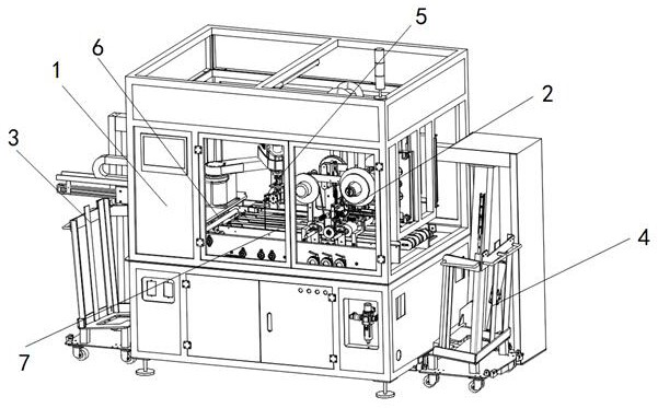
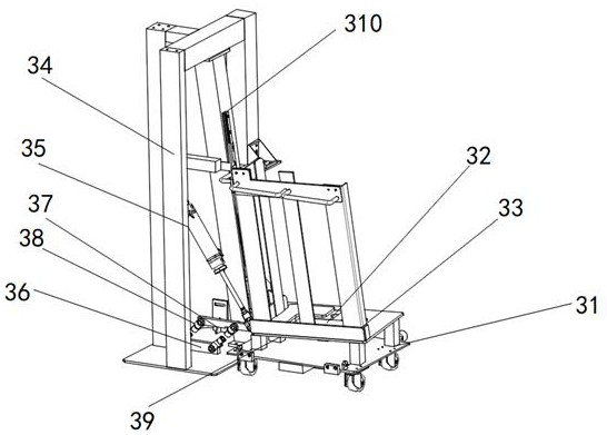
[0031] Embodiment 3 On the basis of Embodiment 1, the protective film feeding device 3 includes a protective film support bottom plate 31, a protective film positioning frame 32, a tray bottom plate 33, a bottom plate pressing assembly, a protective film feeding support frame 34 and a bottom plate Drag assembly; the protective film positioning frame 32 is installed on the protective film support base plate 31, the protective film feeding support frame 34 is installed on one side of the protective film positioning frame 32, and the bottom plate pressing assembly is installed on the protective film The lower end of the feeding support frame 34, the bottom plate drag assembly is installed on the protective film feeding support frame 34; the bottom plate drag assembly includes a rodless cylinder 310, drags a sliding plate, a drag arm and a rectangular tray; The rodless cylinder 310 is installed on the protective film support frame, the drag sliding plate is installed on the rodless...

Embodiment 4

[0032] Embodiment 4 On the basis of Embodiment 3, the base plate pressing assembly includes a telescopic cylinder 35, a pressing positioning plate 36, a pressing rotating plate 37, two pressing rotating shafts 38 and a pressing block 39; the pressing The positioning plate 36 is installed on the protective film feeding support frame 34, and one end of the two pressing rotating shafts 38 is mounted on the pressing positioning plate 36 in rotation, and the pressing rotating plate 37 is installed on the other end of the pressing rotating shaft 38 The fixed end of the telescopic cylinder 35 is fixed on the protective film feeding support frame 34, and the other end is rotatably connected with the compression rotating plate 37, and the compression block 39 is fixed on the right end of the compression rotating plate 37.


PUM


Abstract

The invention discloses a manufacturing device for an antistatic thermal visbreaking protective film. The manufacturing device comprises a manufacturing supporting frame, a protective film tearing mechanism, a protective film feeding device, a protective film discharging device, a protective film cutting mechanism, a grabbing and correcting mechanism and a conveying, adjusting and positioning mechanism. The conveying, adjusting and positioning mechanism is installed in the manufacturing supporting frame, the protective film feeding device and the protective film discharging device are installed on the left side and the right side of the manufacturing supporting frame correspondingly, and the grabbing and correcting mechanism and the protective film tearing mechanism are installed at the left end and the right end of the conveying, adjusting and positioning mechanism correspondingly. The protective film cutting mechanism is mounted on the grabbing and correcting mechanism and comprises a cutting mechanical arm and a protective film cutting device. The device is simple in structure, can efficiently produce cut protective film, greatly improves the production efficiency, and has good market application value.

Description

technical field [0001] The invention relates to the field of automatic assembly, in particular to a manufacturing device for an antistatic thermal adhesion-reducing protective film. Background technique [0002] At present, when manufacturing and transporting optical films such as polarizing plates, retardation plates, lens films for displays, anti-reflection films, hard coat films, transparent conductive films for touch panels, and optical products such as displays using them, A surface protective film is bonded to the surface of the optical film to prevent surface contamination and scratches in subsequent steps. In order to improve work efficiency by saving the labor and time of peeling off the surface protection film and then laminating it, in the visual inspection of the optical film as a product, sometimes the state of the surface protection film is attached to the optical film directly implemented. [0003] Conventionally, in order to prevent the adhesion of scratche...

Claims


Application Information

Patent Timeline
Patent Type & Authority Applications(China)
IPC IPC(8): B65H35/08B65H35/00B65H5/08B65H29/52B26D1/28B26D7/32B32B43/00
CPCB65H35/08B65H35/00B65H5/08B65H29/52B65H35/008B65H35/0073B26D1/285B26D7/32B32B43/006B26D2007/322Y02W30/62
Inventor 赵思银
Owner 东莞市工兴新材料科技有限公司
Why Eureka
Try Eureka