
Wood floor production and manufacturing flatness detection device

A detection device and flatness technology, applied in the direction of mechanical roughness/irregularity measurement, etc., can solve the difficulty of increasing the repair of wooden floors, do not accurately mark the position of the deformation of the wooden floor, and cannot ensure that the repair of the deformed area of ​​​​the wooden floor is completed And other issues

Active Publication Date: 2021-11-02
江苏恒源木业有限公司
View PDF6 Cites 5 Cited by
  • Summary
  • Abstract
  • Description
  • Claims
  • Application Information

AI Technical Summary

Problems solved by technology

[0003] At present, in order to ensure the quality of the products in the processing and production of wooden floors, it is necessary to test the wooden floor, and the flatness detection of the wooden floor is one of the key items. At present, the following problems still exist in the flatness detection process of the wooden floor: a. The existing wooden floor does not accurately mark the deformed position of the wooden floor during the flatness detection process. When the wooden floor is repaired later, it is necessary to find the deformed position of the wooden floor again, which increases the difficulty of repairing the wooden floor. At the same time, during the repair process It is impossible to ensure that all the deformed areas on the wooden floor are repaired, and a second flatness inspection is required; b. The existing wooden floor flatness detection device fails to detect all the end surface areas when detecting the flatness of the wooden floor end surface, There are detection loopholes that lead to incomplete detection of wooden floor end faces

Method used


Image

  • Wood floor production and manufacturing flatness detection device
  • Wood floor production and manufacturing flatness detection device
  • Wood floor production and manufacturing flatness detection device

Examples


Embodiment Construction

[0030] Embodiments of the present invention will be described below with reference to the drawings. In the process, in order to ensure the clarity and convenience of illustration, we may exaggerate the width of the lines or the size of the constituent elements in the diagram.

[0031] In addition, the following terms are defined based on the functions in the present invention, and may be different according to the operator's intention or practice. Therefore, these terms are defined based on the entire content of this specification.

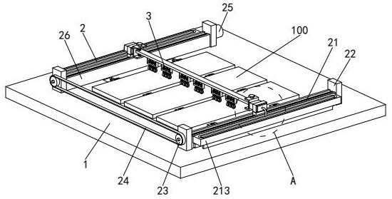
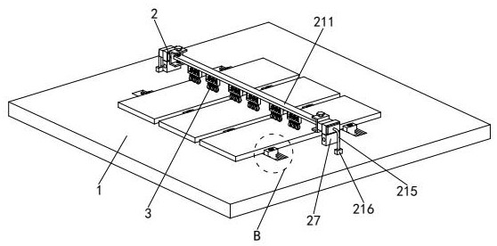
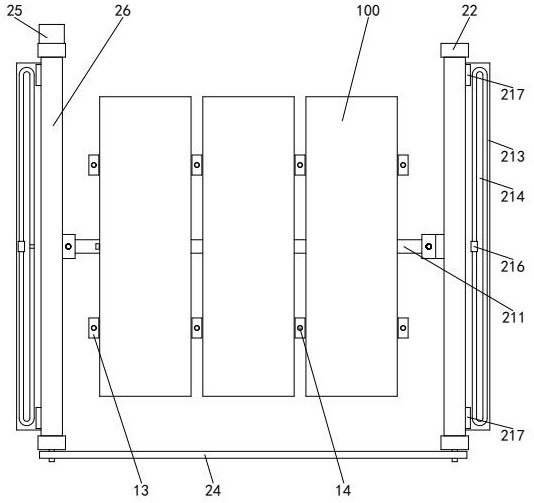
[0032] refer to figure 1 and figure 2 , a wooden floor manufacturing flatness detection device, including a detection platform 1, a driving mechanism 2 and a detection mechanism 3, the detection platform 1 is provided with a driving mechanism 2, and the middle of the driving mechanism 2 is provided with a detection mechanism 3 .

[0033] refer to image 3 and Figure 6, the upper end surface of the detection table 1 is provided with two fro...


PUM


Abstract

The invention relates to the technical field of wood floor detection, in particular to a wood floor production and manufacturing flatness detection device which comprises a detection table, a driving mechanism and a detection mechanism, the driving mechanism is arranged on the detection table, and the detection mechanism is arranged between the left side and the right side of the driving mechanism. The detection mechanism comprises a U-shaped frame, a fixed pipe, a mounting frame, a roller, a first elastic telescopic rod, a mounting block, a marking pipe and a marking branch chain. When flatness detection is carried out on the wood floor, the deformation area of the wood floor can be distinguished and marked, so that the deformation area can be quickly found out when the wood floor is repaired in the later period, the flatness of the surface of the wood floor can be carefully detected, and missing detection of partial area of the surface of the wood floor is prevented, the device can detect the flatness of a plurality of wood floors at the same time, can visually find whether the thicknesses of the wood floors are the same or not in the detection process, and quickly finds out the wood floors with large thickness differences.

Description

technical field [0001] The invention relates to the technical field of wooden floor detection, in particular to a device for detecting the flatness of wooden floor production. Background technique [0002] Wooden floor refers to the floor made of wood. Wooden flooring produced in China is mainly divided into six categories: solid wood flooring, laminate flooring, solid wood composite flooring, multi-layer composite flooring, bamboo flooring and cork flooring, as well as the emerging wood-plastic flooring. . Wood can be sawed, planed, cut, cut and even nailed at will, so it can be used more flexibly in building materials and play its potential role. Warehousing and other related processes. [0003] At present, in order to ensure the quality of the products in the processing and production of wooden floors, it is necessary to test the wooden floor, and the flatness detection of the wooden floor is one of the key items. At present, the following problems still exist in the fl...

Claims


Application Information

Patent Timeline
IPC IPC(8): G01B5/28
Inventor 邱铈涵
Owner 江苏恒源木业有限公司
Learn More