
Shooting system calibration method and device, computer equipment and storage medium

A technology of a shooting system and a calibration method, which can be applied to measurement devices, navigation through speed/acceleration measurement, instruments, etc., and can solve problems such as inaccurate calibration results.

Pending Publication Date: 2021-11-02
SHENZHEN ARASHI VISION CO LTD
View PDF0 Cites 0 Cited by
  • Summary
  • Abstract
  • Description
  • Claims
  • Application Information

AI Technical Summary

Problems solved by technology

[0004] Based on this, it is necessary to address the above technical problems and provide a camera system calibration method, device, computer equipment and storage medium that can solve the problem of inaccurate calibration results

Method used


Image

  • Shooting system calibration method and device, computer equipment and storage medium
  • Shooting system calibration method and device, computer equipment and storage medium
  • Shooting system calibration method and device, computer equipment and storage medium

Examples


Embodiment Construction

[0044] In order to make the purpose, technical solution and advantages of the present application clearer, the present application will be further described in detail below in conjunction with the accompanying drawings and embodiments. It should be understood that the specific embodiments described here are only used to explain the present application, and are not intended to limit the present application.

[0045] It can be understood that the terms "first" and "second" used in this application may be used to describe various technical terms herein, but unless otherwise specified, these technical terms are not limited by these terms. These terms are only used to distinguish one term from another. For example, without departing from the scope of the present application, the third preset threshold and the fourth preset threshold may be the same or different.

[0046]An IMU (Inertial Measurement Unit, inertial measurement unit) and a vision system usually exist in the shooting ...


PUM


Abstract

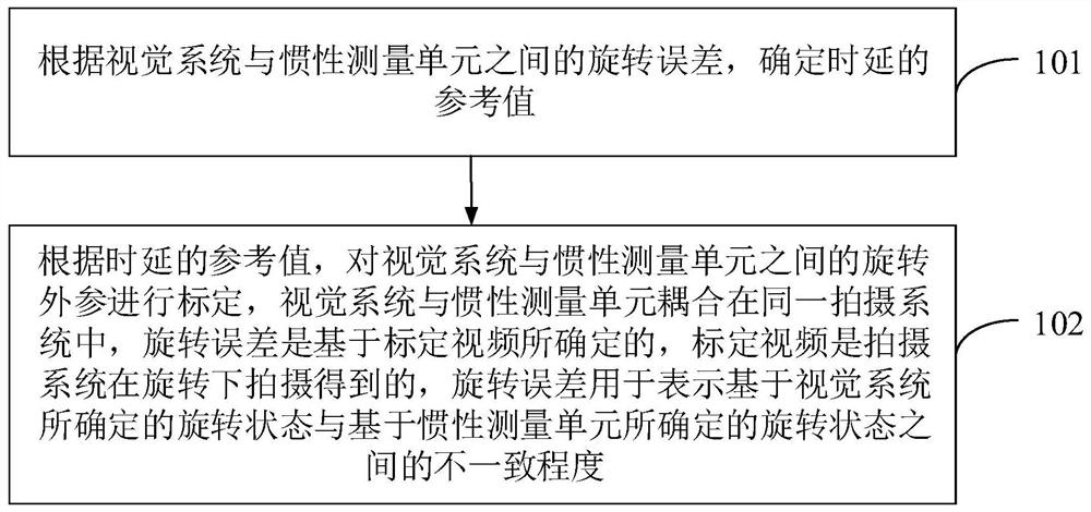
The invention relates to a shooting system calibration method and device, computer equipment and a storage medium. The method comprises the following steps: determining a reference value of time delay according to a rotation error between a visual system and an inertial measurement unit; and according to the reference value of the time delay, calibrating the time delay and rotation external parameters between the visual system and the inertial measurement unit. The visual system and the inertial measurement unit are coupled in the same shooting system, the rotation error is determined based on a calibration video, the calibration video is obtained by shooting of the shooting system under rotation, and the rotation error is used to represent a degree of inconsistency between a rotation state determined based on the visual system and a rotation state determined based on the inertial measurement unit. The reference value of the time delay is determined before the time delay and the rotation external parameter between the visual system and the inertial measurement unit are calibrated, so that the time delay can be prevented from deviating too much, and the situations that the calibration result is not accurate and even the calibration fails due to the fact that the time delay deviation is too large are avoided.

Description

technical field [0001] The present application relates to the technical field of camera calibration, and in particular to a camera system calibration method, device, computer equipment and storage medium. Background technique [0002] An IMU (Inertial Measurement Unit, inertial measurement unit) and a vision system usually exist in the shooting system. For example, a device for positioning and navigation is equipped with a camera system. Among them, it is necessary to take pictures of the surrounding environment through the vision system in the shooting system, and to solve the pose of the device through the IMU in the shooting system. That is to say, the realization of other functions such as positioning and navigation needs to be based on the premise that the relevant parameters between the vision system and the IMU can be accurately determined. Therefore, it is necessary to calibrate the shooting system to determine the relevant parameters between the vision system and ...

Claims


Application Information

Patent Timeline
IPC IPC(8): G01C21/16G01C25/00
CPCG01C21/1656G01C25/005
Inventor 赖东东谢亮谭明朗付伟
Owner SHENZHEN ARASHI VISION CO LTD
Learn More