
Display panel, driving method and display device

A display panel and sub-pixel technology, applied in the direction of identification devices, static indicators, instruments, etc., can solve the problems of time-consuming, picture distortion, etc.

Active Publication Date: 2022-04-19
HKC CORP LTD
View PDF0 Cites 0 Cited by
  • Summary
  • Abstract
  • Description
  • Claims
  • Application Information

AI Technical Summary

Problems solved by technology

[0003] If data signal processing is not performed, in the flip pixel (flip pixel) architecture, when the scanning direction of the display panel is in the opposite direction, the direction of the incoming data is also one forward and one reverse, which will cause distortion of the picture. If data processing is performed, the The timing of the data signal output must correspond to the pixels one by one, and the data signal needs to be set and adjusted before positive and negative scanning, which is very time-consuming

Method used


Image

  • Display panel, driving method and display device
  • Display panel, driving method and display device
  • Display panel, driving method and display device

Examples


Embodiment 1

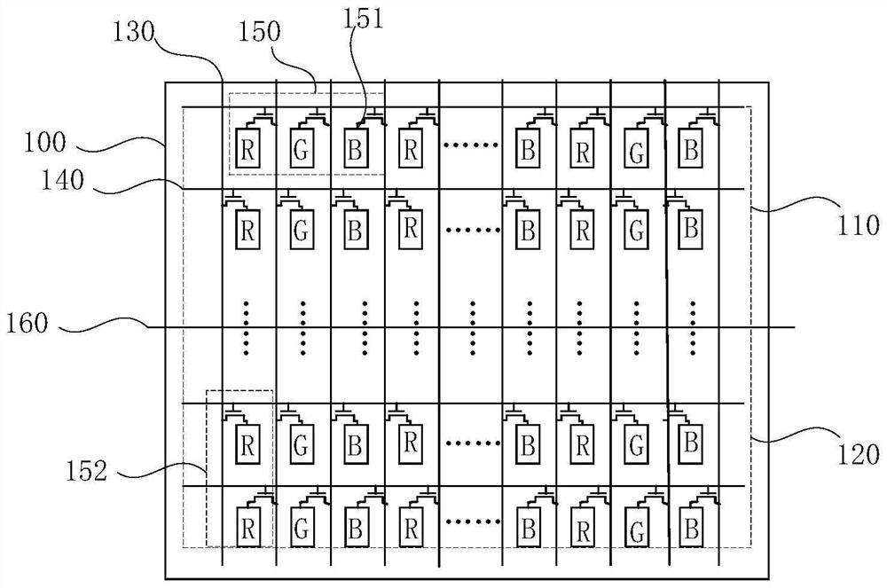
[0038] figure 1It is a schematic diagram of the pixel structure of the display panel of the first embodiment of the present application; as the first embodiment of the present application, a display panel 100 is disclosed, and the display panel 100 includes a plurality of data lines 130 and a plurality of scan lines 140 And a plurality of pixels 150, each of which includes a plurality of sub-pixels 151 of different colors, illustrated with three sub-pixels 151 of different colors, the three sub-pixels 151 of different colors are respectively red sub-pixels (R) , the green sub-pixel (G) and the blue sub-pixel (B), of course, can also be four pixels of different colors, such as RGBW, this application focuses on RGB, but not limited to RGB.

[0039] Further, a plurality of the scan lines 140 and the data lines 130 are interlaced; the sub-pixels 151 are respectively driven by the corresponding data lines 130 and the scan lines 140, wherein, from the first The scanning mode in whi...

Embodiment 2

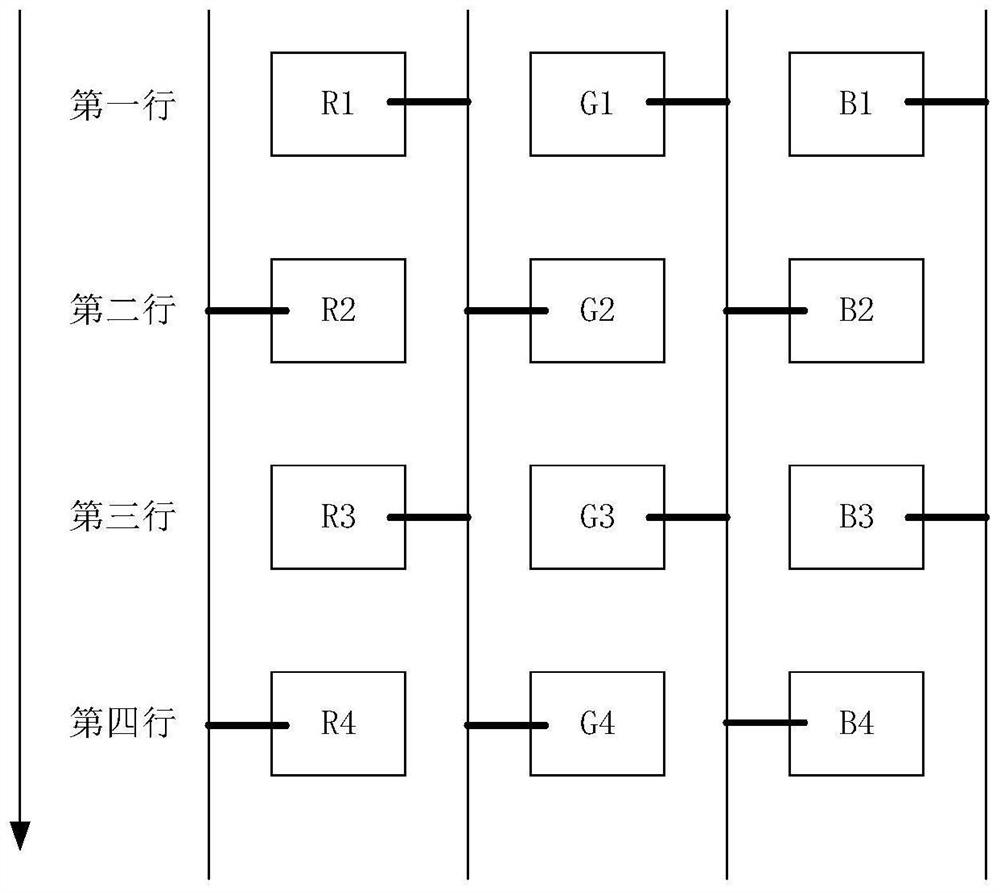
[0045] Figure 4 It is a schematic diagram of the pixel structure of the display panel of the second embodiment of the present application; as the second embodiment of the present application, further refinement is carried out based on the first implementation, such as Figure 4 As shown, the sub-pixel group 152 only includes one sub-pixel 151. To make the pixels in the upper and lower regions symmetrical, it is only necessary to change the arrangement of the sub-pixels in the middle row. In the first region or In the second area 120, in the same column of sub-pixels 151, the sub-pixel 151 corresponding to the last scanning line 140 in the first area 151 and the sub-pixel 151 corresponding to the first scanning line in the second area 120 are The same data line 130 is connected. The data driving signals on the same data line have the same polarity, and the same data line uses the data driving signals with the same polarity, which not only facilitates setting, but also saves p...

Embodiment 3

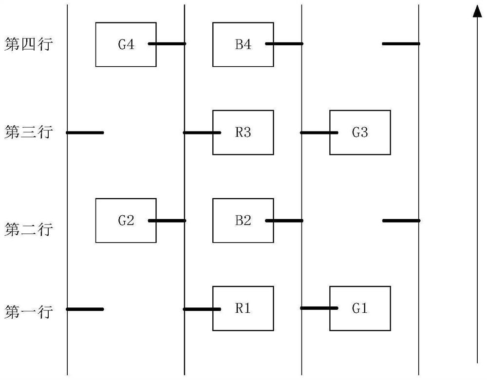
[0051] Figure 7 It is a schematic diagram of the display panel of the third embodiment of the present application; as the third embodiment of the present application, it is also a further refinement of the first embodiment. Different from the above-mentioned second embodiment, each of the sub-pixel groups 152 Including only two sub-pixels 151, in the first region 110 or the second region 120, in the same column of sub-pixels 151, the sub-pixels 151 corresponding to the last two scan lines 140 of the first region 110 and the The sub-pixels corresponding to the first two scan lines 140 in the second region 120 are connected to the same data line 130 .

[0052] Taking four scan lines 140 as a cycle for brief description, in the first area 110, the pixel arrangement and connected data lines of the first scan line and the second scan line are the same, for example, the first scan line The R sub-pixel of the second scan line is connected to the second data line at the same time, t...


PUM


Abstract

The present application discloses a display panel, a driving method and a display device. The display panel is divided into a first area and a second area, and the first area and the second area are arranged along the direction of data lines; The corresponding plurality of sub-pixels are respectively connected to the data lines in one-to-one correspondence; in the first area and the second area, each column of sub-pixels is arranged between two adjacent data lines, and the same column of sub-pixels includes a plurality of sub-pixel groups, one The sub-pixel group includes at least one sub-pixel; among the two adjacent data lines, one of the data lines is connected to the sub-pixels in the odd group, and the other data line is connected to the sub-pixels in the even group. The sub-pixel groups in the area and the corresponding sub-pixel groups in the second area are arranged axisymmetrically with respect to the boundary line between the first area and the second area. Without processing the data signal, forward scanning and reverse scanning of the scanning lines of the display panel can be realized.

Description

technical field [0001] The present application relates to the field of display technology, and in particular to a display panel, a driving method and a display device. Background technique [0002] At present, when using LCD panels, according to the needs of actual display effects, the panel is required to have the function of forward and reverse scanning. For some current panel designs, the starting and ending RGB pixels are arranged in order, and you need to switch to reverse scanning. The scanning mode data read by the timing controller reversely sends the display data to the source driver. [0003] If data signal processing is not performed, in the flip pixel (flip pixel) architecture, when the scanning direction of the display panel is in the opposite direction, the direction of the incoming data is also one forward and one reverse, which will cause distortion of the picture. If data processing is performed, the The timing of data signal output must correspond to the p...

Claims


Application Information

Patent Timeline
Patent Type & Authority Patents(China)
IPC IPC(8): G09G3/36G09G3/20G02F1/1362G09F9/30
CPCG09G3/3655G09G3/20G02F1/1362G09F9/30G09G2320/0209G09G3/3648G09G2300/0452G09G2300/0426G09G2310/0283G09G2310/0202
Inventor 陈杰李建雷袁海江
Owner HKC CORP LTD
Learn More