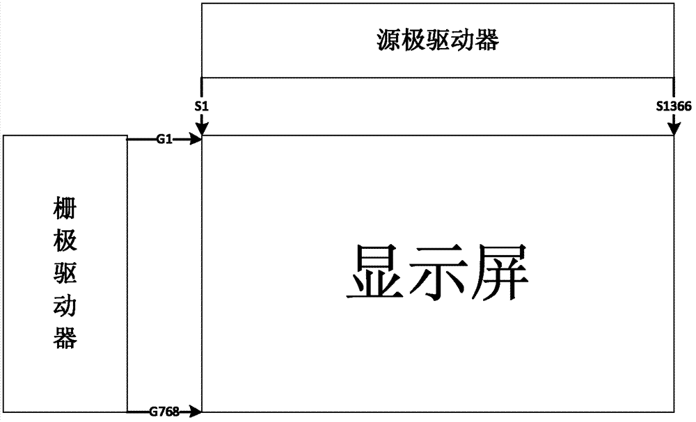
Drive circuit, display screen and electronic equipment
A driving circuit and display technology, which is applied in the electronic field, can solve problems such as the complexity of the system structure, achieve good stability, low cost, and realize the effect of positive viewing
- Summary
- Abstract
- Description
- Claims
- Application Information
AI Technical Summary
Problems solved by technology
Method used
Image
Examples
Embodiment 1
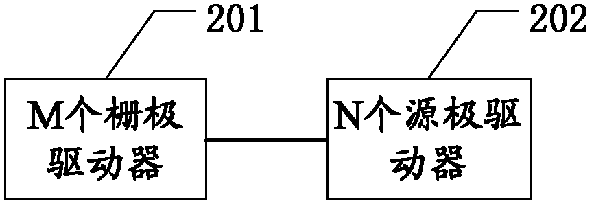
[0039] In this embodiment, a driving circuit 602 is described, such as figure 2 As shown, it includes: M gate drivers 201 and N source drivers 202 .
[0040] Wherein: M gate drivers 201 are connected to the display screen 902, and each gate driver in the M gate drivers 201 includes a first control pin, a second control pin, a third control pin, and a fourth control pin foot.
[0041] Further, the first control pin is used to receive the forward scan control signal, and the second control pin is used to receive the reverse scan control signal.
[0042] Further, the third control pin is connected to the fourth control pin.
[0043] Such as image 3 as shown, image 3 Described is a pin diagram of a gate driver, the gate driver in the background technology only has a first control pin and a second control pin, and image 3 On the basis of the original gate driver, the gate driver in the system adds two new control pins, namely the third control pin and the fourth control pi...
Embodiment 2
[0074] In the second embodiment, a display screen 902 is described, such as Image 6 As shown, it includes a display unit 601 , a driving circuit 602 described in Embodiment 1, a timing controller 603 and N data registers 604 .
[0075] Wherein, the driving circuit 602 is connected to the display unit 601, and the driving circuit 602 includes M gate drivers 201 and N source drivers 202, where M is an integer greater than or equal to 2, and N is an integer greater than or equal to 1.
[0076]The timing controller 603 is connected to the M gate drivers 201 and is used for generating a forward scanning control signal or a reverse scanning control signal for controlling the M gate drivers 201 .
[0077] Further, the timing controller 603 includes: a forward scan control signal pin and a reverse scan control signal pin.
[0078] Further, the forward scan control signal pin is connected to the first control pin of the first gate driver among the M gate drivers 201 . The reverse sc...
PUM
 Abstract
Description
Claims
Application Information
 - R&D
- Intellectual Property
- Life Sciences
- Materials
- Tech Scout
- Unparalleled Data Quality
- Higher Quality Content
- 60% Fewer Hallucinations
Browse by: Latest US Patents, China's latest patents, Technical Efficacy Thesaurus, Application Domain, Technology Topic, Popular Technical Reports.
© 2025 PatSnap. All rights reserved.Legal|Privacy policy|Modern Slavery Act Transparency Statement|Sitemap|About US| Contact US: help@patsnap.com


