Drive circuit, display screen and electronic equipment
What is AI technical title?
AI technical title is built by PatSnap AI team. It summarizes the technical point description of the patent document.
A driving circuit and display technology, which is applied in the electronic field, can solve problems such as the complexity of the system structure, achieve good stability, low cost, and realize the effect of positive viewing
Active Publication Date: 2012-08-01
HISENSE VISUAL TECH CO LTD
View PDF4 Cites 0 Cited by
Summary
Abstract
Description
Claims
Application Information
AI Technical Summary
This helps you quickly interpret patents by identifying the three key elements:
Problems solved by technology
Method used
Benefits of technology
Problems solved by technology
[0008] The invention provides a driving circuit, a display screen and electronic equipment to solve the technical problem in the prior art that the system structure is complicated during reverse scanning
Method used
Image
Click on the blue label to locate the original text in one second.
Reading with bidirectional positioning of images and text.
Examples
Embodiment 1
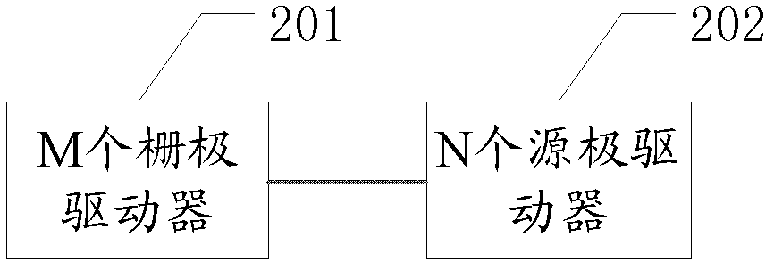
[0040] In this embodiment, a driving circuit 602 is described, such as figure 2 As shown, it includes: M gate drivers 201 and N source drivers 202 .
[0041] Wherein: M gate drivers 201 are connected to the display screen 902, and each gate driver in the M gate drivers 201 includes a first control pin, a second control pin, a third control pin, and a fourth control pin foot.
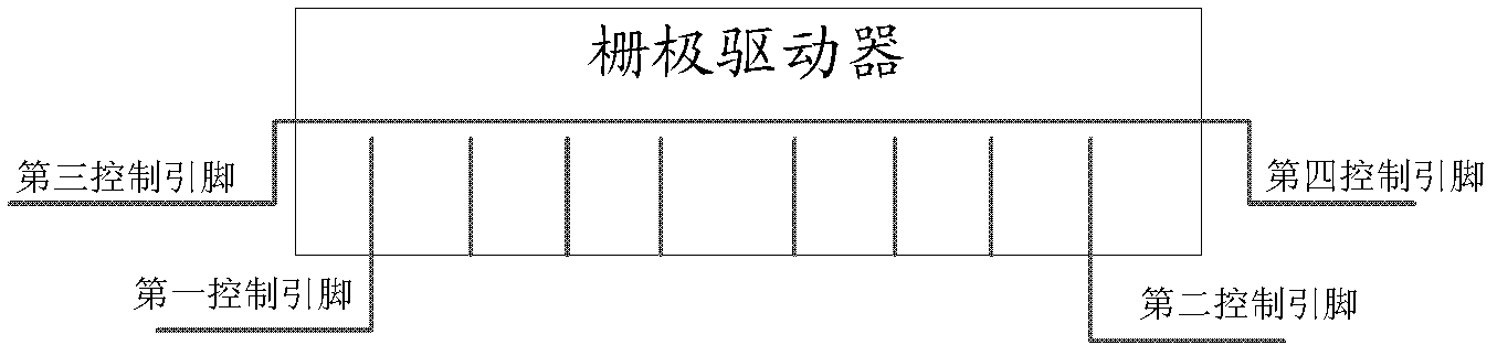
[0042] Further, the first control pin is used to receive the forward scan control signal, and the second control pin is used to receive the reverse scan control signal.
[0043] Further, the third control pin is connected to the fourth control pin.
[0044] like image 3 as shown, image 3 Described is a pin diagram of a gate driver, the gate driver in the background technology only has a first control pin and a second control pin, and image 3 On the basis of the original gate driver, the gate driver in the system adds two new control pins, namely the third control pin and the fourth control pin, ...
Embodiment 2
[0075] In the second embodiment, a display screen 902 is described, such as Image 6 As shown, it includes a display unit 601 , a driving circuit 602 described in Embodiment 1, a timing controller 603 and N data registers 604 .
[0076] Wherein, the driving circuit 602 is connected to the display unit 601, and the driving circuit 602 includes M gate drivers 201 and N source drivers 202, where M is an integer greater than or equal to 2, and N is an integer greater than or equal to 1.
[0077]The timing controller 603 is connected to the M gate drivers 201 and is used for generating a forward scanning control signal or a reverse scanning control signal for controlling the M gate drivers 201 .
[0078] Further, the timing controller 603 includes: a forward scan control signal pin and a reverse scan control signal pin.
[0079] Further, the forward scan control signal pin is connected to the first control pin of the first gate driver among the M gate drivers 201 . The reverse sc...
PUM
Abstract
The invention discloses a drive circuit, a display screen and electronic equipment. The drive circuit comprises M gate drivers and N source drivers, wherein the M gate drivers are connected with the display screen; each of the M gate drivers comprises a first control pin, a second control pin, a third control pin and a fourth control pin; the first control pins are used for receiving positive scanning control signals, and the second control pins are used for receiving reverse scanning control signals; the third control pins are connected with the fourth control pins; the fourth control pin of the ith gate driver is connected with the third control pin of the (i+1)th gate driver; the fourth control pin of the Mth gate driver is connected with the second control pin of the Mth gate driver, M is an integer which is more than or equal to 2, and i is an integer which is more than or equal to 1 and less than M; and the N source drivers are connected with the display screen, and N is an integer which is more than or equal to 1.
Description
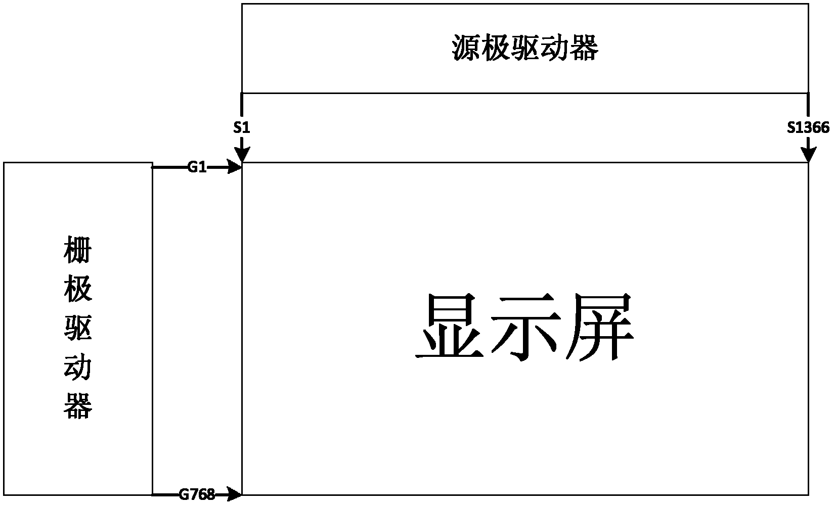
technical field [0001] The invention relates to the field of electronic technology, in particular to a driving circuit, a display screen and electronic equipment. Background technique [0002] TFT (Thin Film Transistor, Thin Film Field EffectTransistor) liquid crystal panel realizes image transmission through fixed gate driver scanning mode and source driver transmission mode, such as figure 1 as shown, figure 1 The 60HZ 1366*768 panel described in , the forward scanning method of the panel is from top to bottom, from left to right, so that the scanning direction of the corresponding gate driver is G1→G768, that is, scanning from top to bottom, corresponding to The transmission direction of the source driver shift register is S1→S1366, that is, scanning from left to right. [0003] It can be seen that the scanning direction of the above-mentioned panel is relatively single, and this singleness of the display direction also proposes a fixed structural design for the struct...
Claims
Application Information
Patent Timeline
Application Date:The date an application was filed.
Publication Date:The date a patent or application was officially published.
First Publication Date:The earliest publication date of a patent with the same application number.
Issue Date:Publication date of the patent grant document.
PCT Entry Date:The Entry date of PCT National Phase.
Estimated Expiry Date:The statutory expiry date of a patent right according to the Patent Law, and it is the longest term of protection that the patent right can achieve without the termination of the patent right due to other reasons(Term extension factor has been taken into account ).
Invalid Date:Actual expiry date is based on effective date or publication date of legal transaction data of invalid patent.

