

A Relay with Instantaneous Voltage Loss Protection
A voltage-loss protection and relay technology, applied in the direction of relays, electromagnetic relays, detailed information of electromagnetic relays, etc., can solve the problems of high UPS power supply costs, difficult on-site transformation, and affecting the timeliness of automatic control, etc.
- Summary
- Abstract
- Description
- Claims
- Application Information
AI Technical Summary
Problems solved by technology
Method used
Image

Examples
Embodiment Construction
[0042] The following will clearly and completely describe the technical solutions in the embodiments of the present invention with reference to the accompanying drawings in the embodiments of the present invention. Obviously, the described embodiments are only some, not all, embodiments of the present invention. Based on the embodiments of the present invention, all other embodiments obtained by persons of ordinary skill in the art without making creative efforts belong to the protection scope of the present invention.
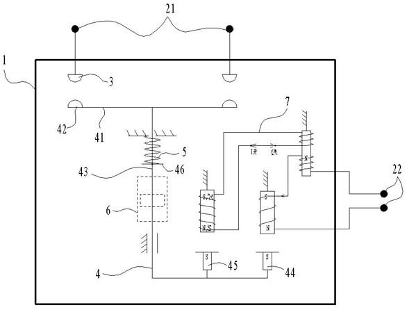
[0043] Such as figure 1 As shown, a relay with instantaneous voltage loss protection, the relay includes a housing 1, a main terminal 21, a control current terminal 22, an independent contact 3, an electrical contact 4, a main return spring 5, and a step displacement assembly 6. Electromagnet assembly 7,
[0044] The independent contact 3, the electric contact 4, the main return spring 5, the step displacement assembly 6, and the electromagnet assembly 7 are ...
PUM
 Abstract
Description
Claims
Application Information