A kind of descaling system in copper tube of condenser

A technology for condensers and copper tubes, which is applied in the field of descaling systems in copper tubes of condensers, to achieve the effects of facilitating condensation adhesion, increasing contact area, and prolonging working time

Active Publication Date: 2021-05-18
周利杰
View PDF10 Cites 0 Cited by
  • Summary
  • Abstract
  • Description
  • Claims
  • Application Information

AI Technical Summary

Problems solved by technology

[0005] In order to solve the problem of scale cleaning in the condensing copper tube of our company's condenser, the present invention provides a scale removal system in the copper tube of the condenser. The main body of the scale removal system is a metal wire connected to the positive and negative poles of the DC power supply respectively The two wire meshes are respectively located in the two condensed water converging chambers, and a number of arc-shaped electrode plates extending into the condensing copper tubes are respectively arranged on the two wire meshes, so that each condensing copper tube forms a relative The positive plate and the negative plate are set up, so that an electric field is formed after energization, and then the metal ions in the condensed water move to the negative plate and form scales to adhere to the negative plate, preventing it from condensing on the inner wall of the condensing copper tube. When cleaning, It only needs to take out the wire mesh and the negative plate and replace them with new ones, which greatly improves the cleaning efficiency

Method used


Image

  • A kind of descaling system in copper tube of condenser
  • A kind of descaling system in copper tube of condenser
  • A kind of descaling system in copper tube of condenser

Examples


Embodiment 1

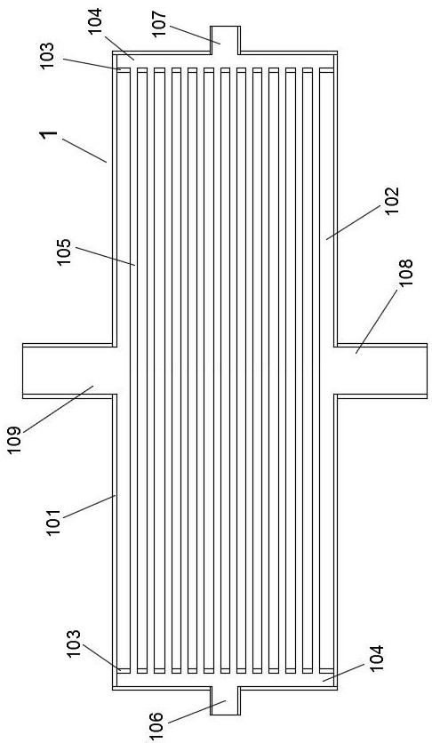
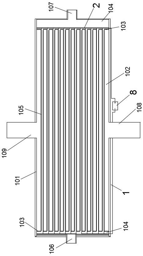
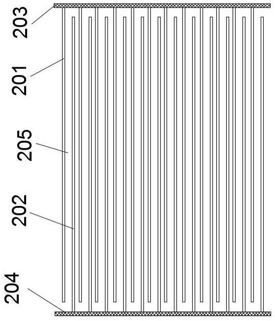
[0054] Such as Figure 2-6 As shown, a descaling system in the copper tube of the condenser, the descaling system 2 is set in the two condensed water converging chambers 104 of the condenser 1, and includes positive metal filters connected to the positive and negative poles of the DC power supply 8 respectively Net 203 and negative electrode metal filter screen 204, wherein, the positive electrode metal filter screen 203 is arranged in the condensed water converging cavity 104 that communicates with the condensed water inlet 107, and there are several arc-shaped positive plates 201 distributed thereon, and these positive plates 201 corresponds to the position and quantity of the condensing copper tubes 105 in the condenser 1 one by one, and extends into the corresponding condensing copper tubes 105 and extends to the other end of the condensing copper tubes 105; the negative metal filter screen 204 It is arranged in the condensed water converging cavity 104 communicated with t...

Embodiment 2

[0059] This embodiment is an improvement made on the basis of Embodiment 1, and its basic structure is the same as that of Embodiment 1, and the improvements are as follows: Figure 7 As shown, the arc-shaped inner walls of the positive electrode plate 201 and the negative electrode plate 202 are oppositely arranged, and arc-shaped recesses 208 and arc-shaped convex ribs 207 extending along the length direction are alternately distributed on the arc-shaped inner walls of the two.

Embodiment 3

[0061] This embodiment is an improvement made on the basis of Embodiment 1, and its basic structure is the same as that of Embodiment 1. The improvement is that the positive plate 201 and the negative plate 202 are metal tungsten plates with a thickness of 1-1.5 mm. , and the surface of the metal tungsten plate is covered with magnesium oxide coating, the coating thickness is 0.2-0.5mm.


PUM

PropertyMeasurementUnit
thicknessaaaaaaaaaa
coating thicknessaaaaaaaaaa
thicknessaaaaaaaaaa

Abstract

A descaling system in the copper tube of a condenser, the descaling system includes a positive metal filter and a negative metal filter respectively connected to the positive and negative DC power supply, the positive metal filter is distributed with a positive plate, and the negative metal filter is distributed There is a negative plate, and the positive and negative plates in each condensing copper tube are symmetrically distributed along the axial direction of the condensing copper tube, so that a vertical electric field area is formed between the two after they are energized. After electrification, the present invention forms an electric field region between the two pole plates of each copper tube, and then makes the metal ions in the condensed water move to the negative plate and gather at the negative plate. At this time, under the action of heat exchange, it can form Scale adheres to the negative plate to avoid condensation on the inner wall of the condensation copper tube. When cleaning, only the wire mesh and negative plate need to be taken out and replaced with new ones, which greatly improves the cleaning efficiency.

Description

technical field [0001] The invention relates to a condenser in the field of steam power generation in thermal power plants, in particular to a scale removal system in copper tubes of the condenser. Background technique [0002] The condenser is a heat exchanger that condenses the exhaust steam of the steam turbine into water, also known as the rehydrator. The existing condensers of our company are all water-cooled condensers, and their structures are as attached figure 1 As shown, the condenser 1 is a fully-enclosed hollow cylindrical shell 101, and a sealing plate 103 is respectively arranged at the positions close to both ends in the diameter direction, and a condensation zone 102 is formed between the two sealing plates 103, and the two sealing plates 103 Two condensed water converging cavities 104 are formed between the two ends, and a number of condensed copper tubes 105 are densely distributed in the condensed area 102. The two ends of these condensed copper tubes 105...

Claims


Application Information

Patent Timeline
Patent Type & Authority Patents(China)
IPC IPC(8): F28F19/00F28F19/01F28G13/00F28G9/00F28G15/00
CPCF28F19/004F28F19/01F28G9/00F28G13/00F28G15/003
Inventor 周利杰马拴长古江华张留峰岳威
Owner 周利杰
Why Eureka
Try Eureka