Breath analyzer

a breath analyzer and breath sample technology, applied in the field of breath analyzers, can solve the problems of time-consuming testing procedures, sober drivers will not accept cumbersome breath sampling, and the device should operate with maintained accuracy, and achieve the effect of ensuring the accuracy of breath sampling

Active Publication Date: 2008-03-13
SENSEAIR
View PDF14 Cites 57 Cited by
  • Summary
  • Abstract
  • Description
  • Claims
  • Application Information

AI Technical Summary

Problems solved by technology

The reliability, speed and ease with which breath sampling can be accomplished is, of course, a central issue.
Only a very small fraction of samples will actually result in the positive detection of alcohol, and sober drivers will not accept a cumbersome, and time-consuming testing procedure.
A further complication is that such a device should operate with maintained accuracy also at extreme environmental conditions.
Mouthpieces are disposable items for hygienic reasons, and their handling and cost are major limitations to the widespread use of breath analysing equipment in e g alcohol interlock systems.
On the other hand, it is more complex and expensive, especially when a plurality of substances are involved.
A technological challenge not solved in state-of-the-art infrared spectrometers is to combine high measurement resolution with fast response.
As already pointed out, these requirements are in opposition.
Further difficulties are related to the legal aspects related to the collection and analysis of breath samples from human subjects.
The demands on reliability and traceability of eventual errors are exceptionally high.
A difficulty specifically related to the analysis of breath samples, and the simultaneous CO2 measurement, is the fact that the CO2 concentration in breath samples is typically in the percent range, whereas the concentration of other substances is typically several orders of magnitude lower.
It is thus necessary to minimise cross sensitivities, i e the interdependencies between the various determinations, and the large difference in concentrations is a complication.

Method used


Image

  • Breath analyzer
  • Breath analyzer
  • Breath analyzer

Examples


Embodiment Construction

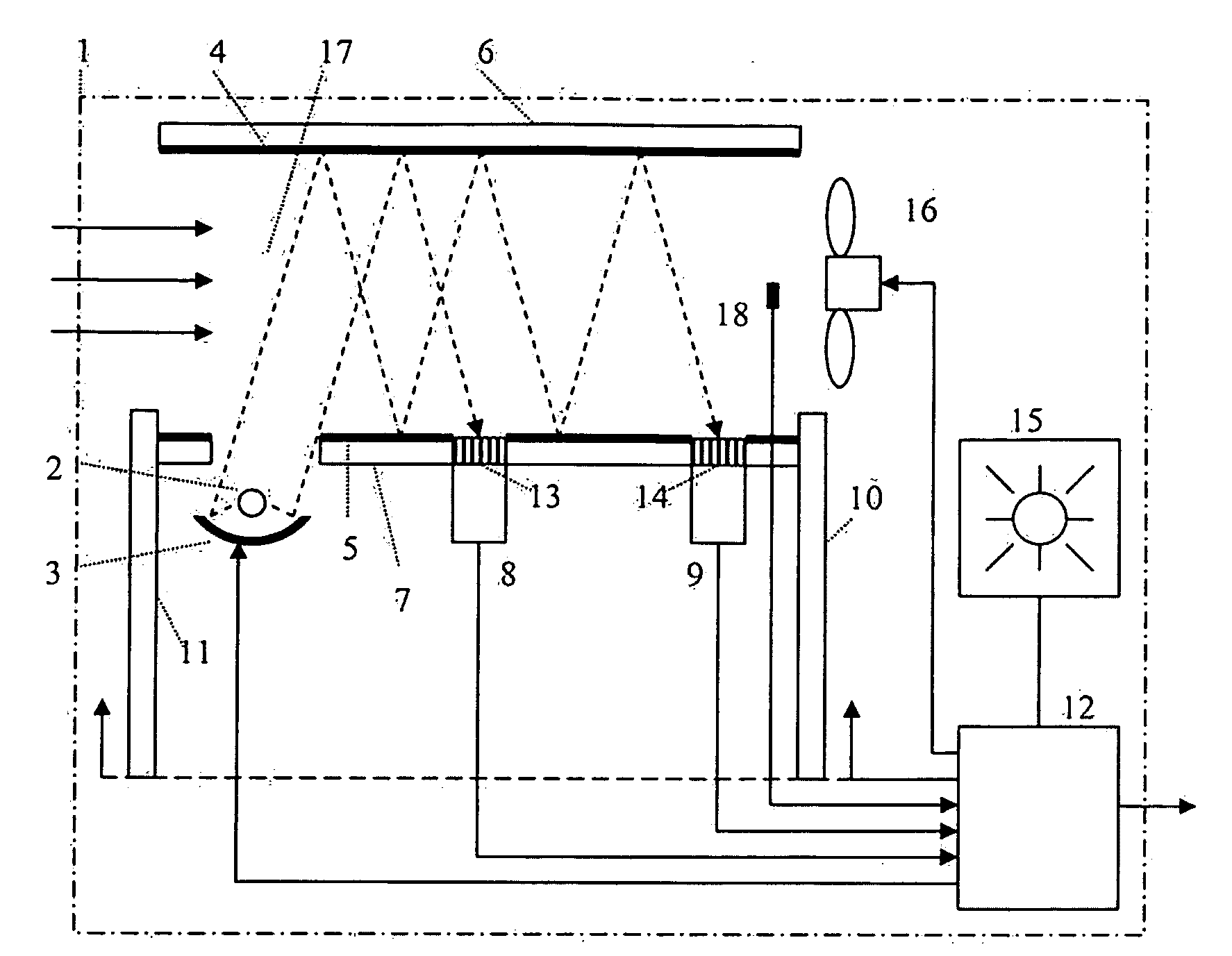
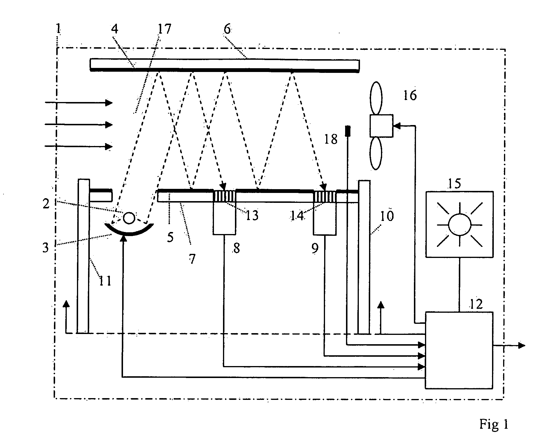
[0056]One preferred embodiment of the system according to the invention is schematically depicted in FIG. 1. All system elements are being confined in a physical enclosure 1, the size of which is relatively modest, typically less than 100×50×40 mm, due to the miniaturization and small size of most of the included elements. The enclosure could be adapted and designed for mobile use, e g as a handheld unit, or stationary installation, e g in a vehicle.

[0057]A mechanical support structure 6, 7 defines a measuring cell 17 is provided with surfaces 4, 5 of high infrared reflectance, e g by being plated with a thin gold film, exhibiting a reflection coefficient for infrared radiation of 0.95 or higher. The support structure 6, 7 is used for precision positioning of a radiation source 2, a concave reflector 3, dispersive elements, e g interference filters, 13, 14, detectors 8, 9, e g thermopile or pyroelectric elements.

[0058]The optical arrangement of the measuring cell 17, including the s...


PUM


Abstract

A system for the detection and analysis of at least one volatile substance in breath samples of a subject, including at least one source of infrared radiation adapted to the wavelength range of specific absorption peaks of said substances, a plurality of reflecting surfaces of said radiation adapted for collimation onto at least one detector providing a plurality of electrical output signals corresponding to the transmission of said radiation within wavelength intervals corresponding to said absorption peaks, at least one measuring cell including a mechanical support structure defining the position of said source, reflecting surfaces and detector, adapted to the reception and disposal of said breath sample, and exposing it to said radiation, at least one electronic signal processing unit with capacity to analyse said signals with respect to pre-programmed information concerning infrared absorption spectra of said substances. The response of the system being displayed or otherwise communicated, and perceived as essentially instantaneous.

Description

CROSS REFERENCE TO RELATED APPLICATION[0001]This application claims priority to GB 06 8051.7 filed Sep. 13, 2006 which is currently pending.FIELD OF THE INVENTION[0002]The present invention is concerned with the detection and analysis of substances within breath samples from subjects. One field of application of significant importance is the determination of alcohol concentration in vehicle drivers, but the field encompasses the detection of any volatile substance for any reason in breath samples. Technologically, it is preferred to use the present invention with those volatile substances exhibiting distinctive absorption properties of infrared radiation, thus allowing their identification and quantification.BACKGROUND[0003]It is generally known that the constitution of undiluted samples of air expired from the lungs of a subject is tightly linked to the corresponding blood constitution. This is due to the extremely large surface area of normal lung tissue, including the alveoli com...

Claims


Application Information

Patent Timeline
Patent Type & Authority Applications(United States)
IPC IPC(8): G01J5/02
CPCB60K28/06B60W2540/24G01N21/0332G01N2201/06186G01N33/497G01N33/4972G01N21/3504G01N21/031G01N21/05
Inventor HOK, BERTILPETTERSSON, HAKAN
Owner SENSEAIR
Why Eureka
Try Eureka