
Refrigeration unit condensation prevention

a refrigeration unit and condensation prevention technology, applied in the field of frame and/or door heating, can solve the problems of causing correspondingly high energy costs, affecting the efficiency of refrigeration units, so as to prevent condensation from forming, reduce energy consumption, and eliminate door and frame condensation.

Active Publication Date: 2007-04-24
GEUKE BRADLEY W
View PDF11 Cites 65 Cited by
  • Summary
  • Abstract
  • Description
  • Claims
  • Application Information

AI Technical Summary

Benefits of technology

[0006]The purpose of the apparatus, systems and methods of this invention is to efficiently eliminate door and frame condensation at widely utilized commercial freezer / refrigeration display cases. The invention is proactive in preventing condensation from forming by activating frame / door heaters before the dew point temperature at frame and door surfaces is reached. Power is then cycled off at a set point above dew point to save energy. This is accomplished by configuring apparatus of this invention to provide highly accurate sensing of frame temperature and dew point by thermally isolating temperature sensors and constantly updating data to reliably provide the ability to accurately anticipate condensation at case surfaces. The invention eliminates door damage and runoff safety hazards due to condensation build-up, efficiently cycles duty time of frame / door heaters thus lowering the installation's energy costs, and requires no expensive countermeasures to maintain accuracy and efficacious performance.
[0011]It is therefore an object of this invention to provide apparatus, systems and methods for efficient elimination of door and frame condensation at widely utilized commercial freezer / refrigeration display cases.
[0012]It is another object of this invention to provide apparatus, systems and methods for elimination of door and frame condensation at freezer / refrigeration display cases that proactively prevents condensation from forming by activating frame / door heaters before dew point temperature at frame and door surfaces is reached.
[0013]It is still another object of this invention to provide apparatus for efficient elimination of door and frame condensation at freezer / refrigeration display cases that are configured to accurately sense frame temperature and dew point by thermally isolating temperature sensors and that are constantly data updated to reliably provide the ability to accurately anticipate condensation at case surfaces.
[0014]It is yet another object of this invention to provide apparatus, systems and methods utilized with freezer / refrigeration display cases that eliminate door damage and runoff safety hazards due to condensation build-up, efficiently cycle duty time of frame / door heaters thus lowering the installation's energy costs, and require no expensive countermeasures to maintain accuracy and performance of the apparatus and systems.
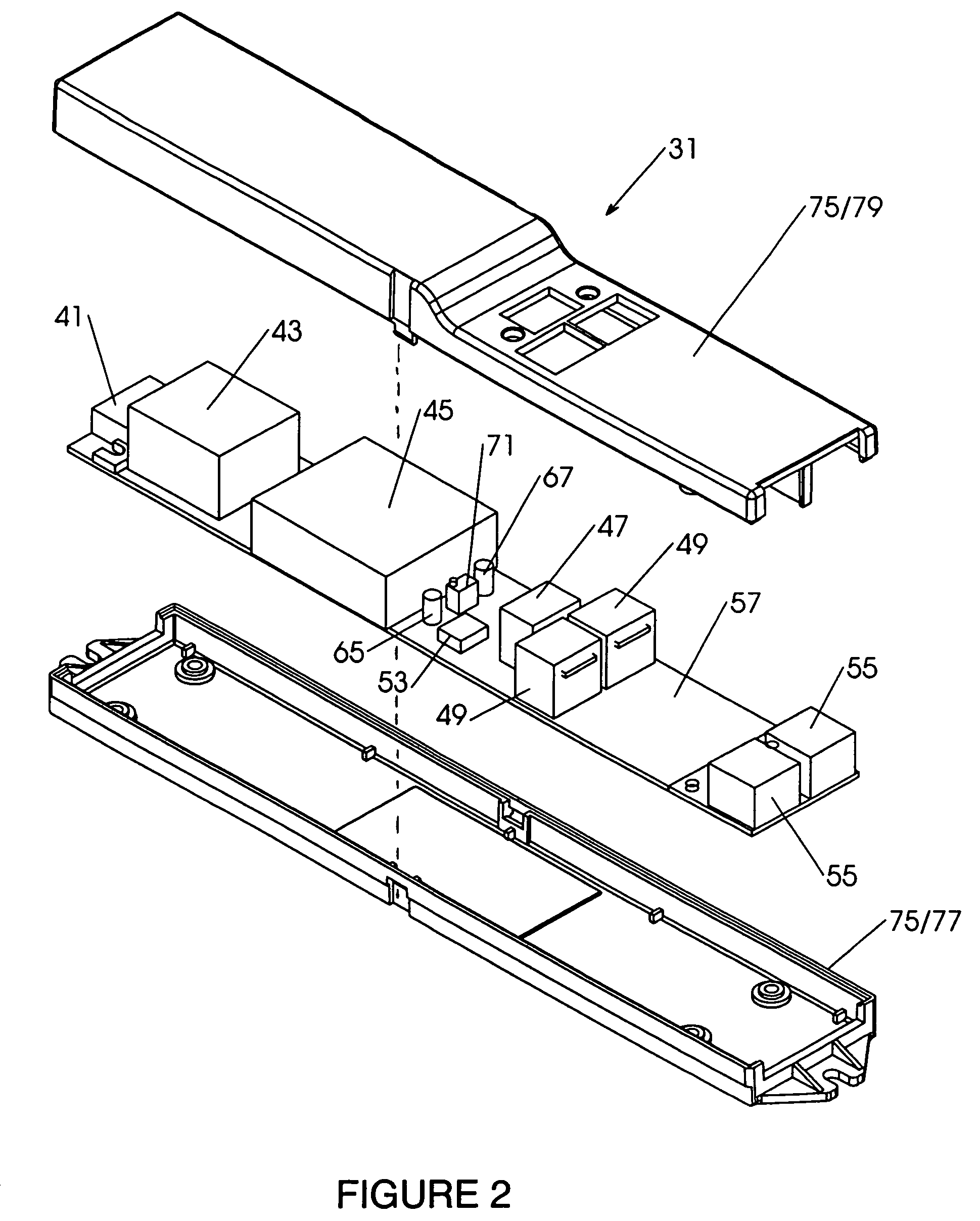
[0015]It is another object of this invention to provide condensation control apparatus for a refrigerated display case having at least one door, a frame and at least one frame / door heater, the apparatus including a frame temperature sensing unit adapted for monitoring temperature of one of the display case door or display case frame and including a carrier having a temperature sensor thereat, a dew point sensing unit adapted for monitoring ambient air temperature and relative humidity outside of the display case and including a carrier having at least one dew point sensing component thereat, a control unit connected with the sensing units and including processing means connected for activating the display case frame / door heater when monitored display case door or frame temperature drops below a preselected set point above a dew point value derived from monitored ambient temperature and relative humidity, and housing means for locating the sensing units including structure establishing thermal isolation of the sensing units by minimizing heat transfer contacts between the sensing units and the housing means and locating the temperature sensor and the at least one dew point sensing component amid insulating air pockets formed by the structure of the housing means.

Problems solved by technology

Condensation build up on commercial refrigeration display case doors can cause door damage and presents a safety hazard if runoff from the door(s) and / or case frames accumulates on adjacent floors.
Currently, in most commercial installations, in order to prevent excessive condensation build-up at display case doors and frames, the doors and frames are heated utilizing internal frame heaters operating at 100% duty cycle time (and incurring correspondingly high energy costs).
These devices have, however, not always proven successful.
For example, detector failure due to environmental contamination or poor manufacturing tolerances of moisture sensors in general is common.
Such detector failure can result in either frame / door heaters remaining off (thus failing to inhibit dangerous condensation build-up and runoff) or the heaters remaining on (thereby achieving no energy savings).
Moreover, such devices are merely reactive, activating heaters only after potentially damaging and dangerous condensation has formed.
Such devices and systems have not proven altogether successful, however, due to inaccuracy of temperature readings, particularly where both cold and warm environments are adjacent one another such as is found at commercial freezer / refrigeration display cases.
Failure to configure such systems to enhance accuracy of readings has resulted in erratic condensation control, on some occasions wasting energy unduly heating frames / doors, on other occasions responding late or otherwise inadequately to condensation formation, and / or on still other occasions failing to control appropriate heater cycling (i.e., shut-off) with consequent loss of efficiencies.
This approach, however, is not feasible in large commercial freezer display installations where size and space are limited and where the cost for such counter measures are not easily absorbed (and not likely to be tolerated).

Method used


Image

  • Refrigeration unit condensation prevention
  • Refrigeration unit condensation prevention
  • Refrigeration unit condensation prevention

Examples


Embodiment Construction

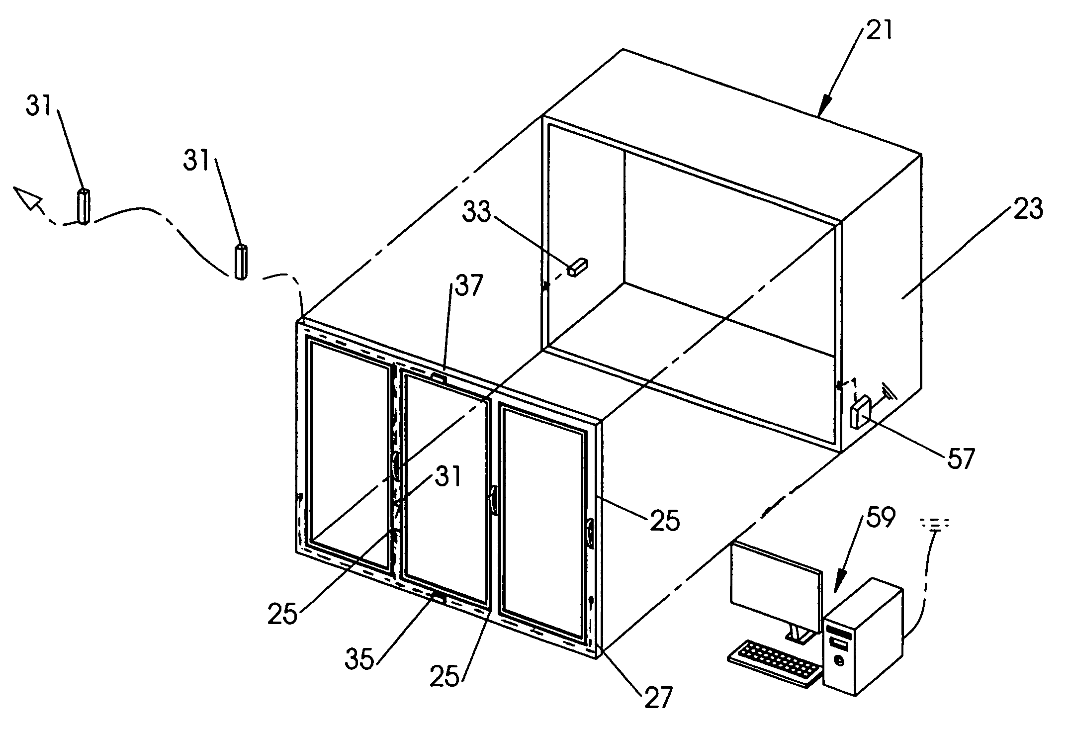
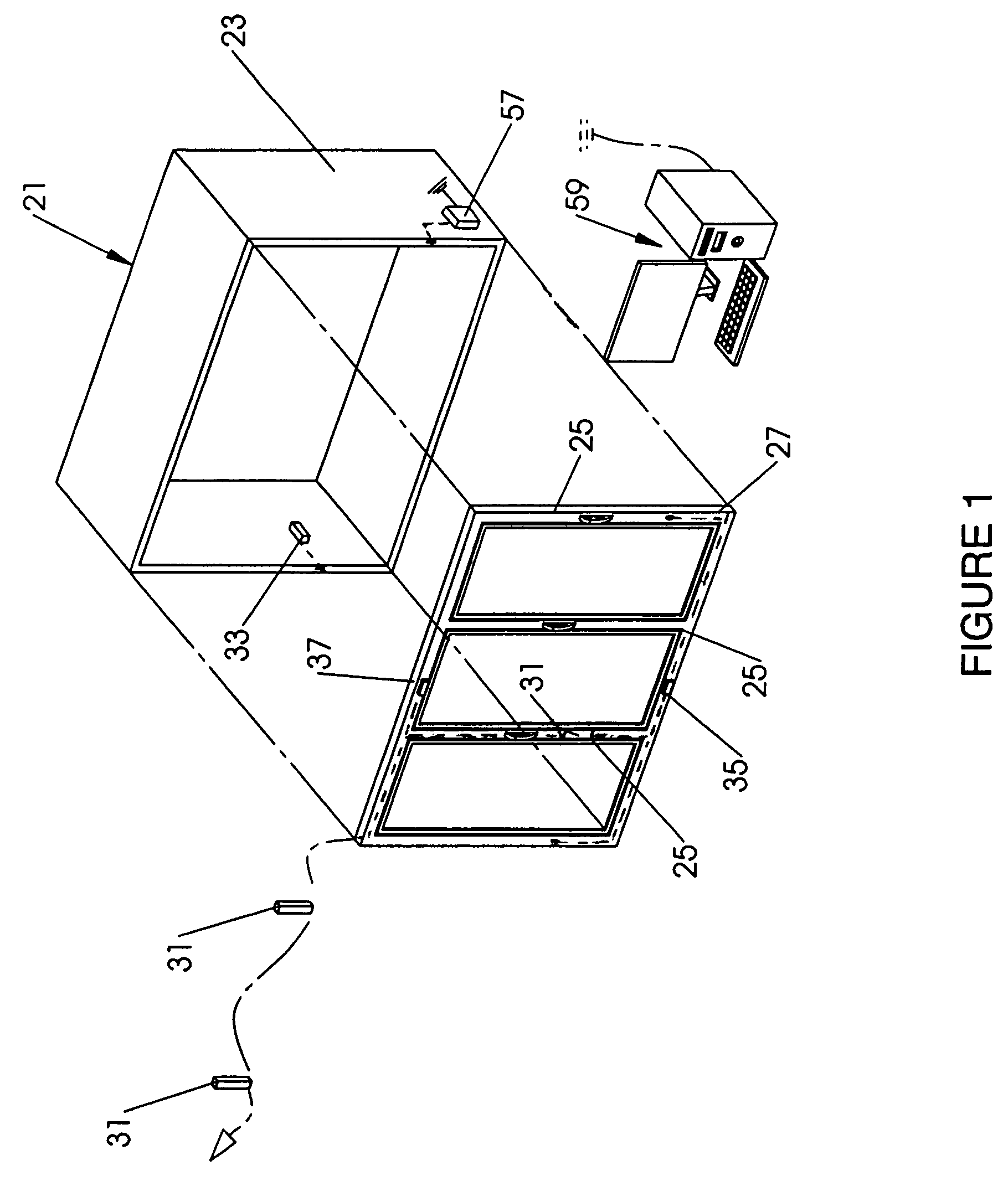
[0035]The system of this invention is illustrated in FIG. 1 in association with a common commercial freezer / cooler display unit 21 including a display container 23 having a frame (not shown in this FIGURE) and doors 25 in frame 27 (hereinafter, refrigeration case(s)). Up to fifteen such cases 21 can be served by the system as currently configured (though greater or fewer cases could be accommodated). Each case 21 is provided with a local controller unit 31 connected with an array of case sensors including internal case temperature sensor 33, external case frame temperature sensor 35 and dew point sensor 37. The array of sensors may be hard wired (as shown herein) to unit 31 at each case 21 through frame members, or may be configured to function wirelessly utilizing known technologies. While separate frame temperature and dew point sensors 35 and 37 are shown in this FIGURE, an alternate configuration that combines both sensors into one housing is shown hereinafter. Sensor mounting p...


PUM


Abstract

Apparatus, systems and methods are disclosed for efficient elimination of door and frame condensation at widely utilized commercial freezer / refrigeration display cases. The apparatus includes a local controller unit connected with an array of case sensors including an internal case temperature sensor, an external case frame temperature sensor and a dew point sensor. The case frame temperature sensor and dew point sensor are housed to thermally isolate sensing elements thereof from effects of frame temperature changes and ambient air temperature in the vicinity of a sensing element, and to limit heat transfer by the housing to the sensing elements thereby improving sensing accuracy and apparatus performance.

Description

FIELD OF THE INVENTION[0001]This invention relates to frame and / or door heating to remediate condensation build-up in refrigerated display cases, and, more particularly, relates to sensing and operating devices and methods for activation and deactivation of such heating.BACKGROUND OF THE INVENTION[0002]Condensation build up on commercial refrigeration display case doors can cause door damage and presents a safety hazard if runoff from the door(s) and / or case frames accumulates on adjacent floors. Currently, in most commercial installations, in order to prevent excessive condensation build-up at display case doors and frames, the doors and frames are heated utilizing internal frame heaters operating at 100% duty cycle time (and incurring correspondingly high energy costs).[0003]Devices have been heretofore suggested and / or utilized to control condensation without running heaters at 100% duty cycle times. One approach has utilized a detector to directly sense the presence of condensat...

Claims


Application Information

Patent Timeline
Patent Type & Authority Patents(United States)
IPC IPC(8): A47F3/04
CPCA47F3/0426F25D21/04F25D29/005F25B2700/02F25D2700/12F25D2700/14
Inventor MURRAY, BRENT W.BERTSCH, PATRICK M.MAJZNER, ROBERT A.
Owner GEUKE BRADLEY W
Learn More