Wireless transponder and image forming device

a technology of image forming device and wireless transponder, which is applied in the direction of electrical signalling details, mechanical actuation of burglar alarms, instruments, etc., can solve the problems of inability to satisfactorily provide a signal cable to an object in motion such as a moving or rotating object, electromagnetic waves are not able to satisfactorily travel within a range of several cm (centimeters), and wireless transponders cannot function satisfactorily. , to achieve the effect o

Active Publication Date: 2012-08-07
FUJIFILM BUSINESS INNOVATION CORP
View PDF29 Cites 1 Cited by
  • Summary
  • Abstract
  • Description
  • Claims
  • Application Information

AI Technical Summary

Benefits of technology

[0022]The wireless transponder according to any of the above aspects of the invention allows signals to propagate as acoustic waves inside the delay unit, to thereby enable use of a low-frequency signal. Accordingly, wireless signals may be extracted satisfactorily even in environment that is surrounded by metal. Further, the wireless transponder has a simple structure which enables downsizing and cost reduction. Further, highly accurate sensing may be achieved in an environment surrounded by metal, and also in remote locations by using a function of sensing a physical or chemical characteristics as a delay unit.

Problems solved by technology

However, the structure of signal cables that are used for such a purpose gives rise to a problem, in that it becomes difficult to provide a signal cable to an object in motion such as a moving or rotating object, inside a very small space such as a blood vessel, or in a chemically or biologically harsh environment.
Consequently, in a case that the wireless transponders used are surrounded by metal, the electromagnetic waves are not able to satisfactorily travel within a range of several cm (centimeters) or so due to the short length of the electromagnetic waves.
That is, there exists a problem that the wireless transponders do not function satisfactorily.
In another case of using an electromagnetic wave having a low frequency of several 100 kHz, a wavelength of the electromagnetic wave is as long as several km (kilometers) or more; but in this case, a problem arises in that their use makes it difficult to form a small antenna of a radiative emission type.
However, when used in an environment that is surrounded by metal, smooth propagation of signals is hindered by absorption of magnetic fields, as mentioned above.

Method used


Image

  • Wireless transponder and image forming device
  • Wireless transponder and image forming device
  • Wireless transponder and image forming device

Examples


first embodiment

[0062

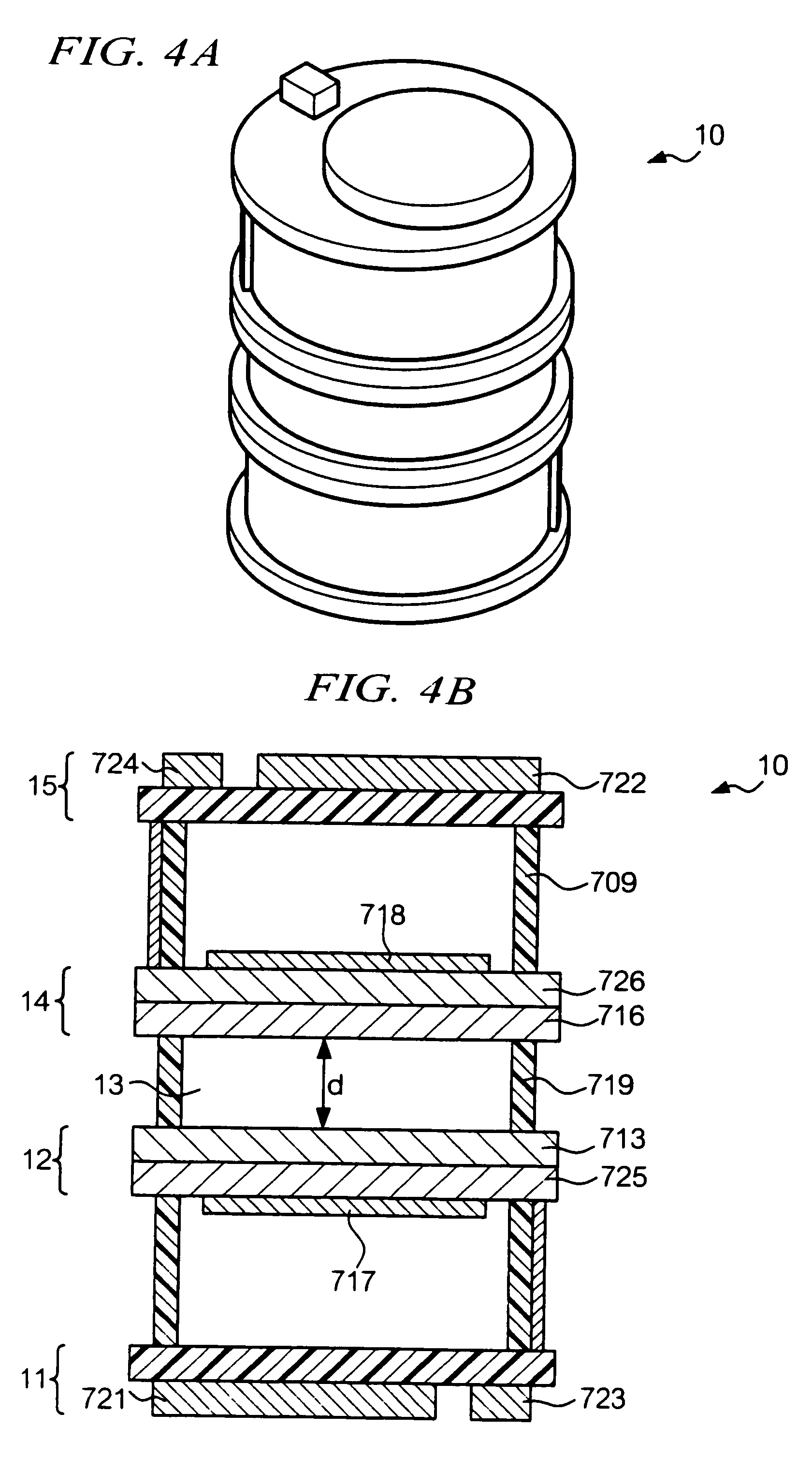
[0063]FIG. 7A is a sectional view showing a device structure of a wireless transponder 100a according to the first embodiment. FIG. 7B is a sectional view showing a device structure of another wireless transponder 100b according to this embodiment. The wireless transponders 100a and 100b have the same structure except that delay media (delay media 101a and 101b) have different thicknesses. Suffixes a and b added to reference numerals will be omitted from the following description where related members need not particularly be distinguished from each other by the suffixes.

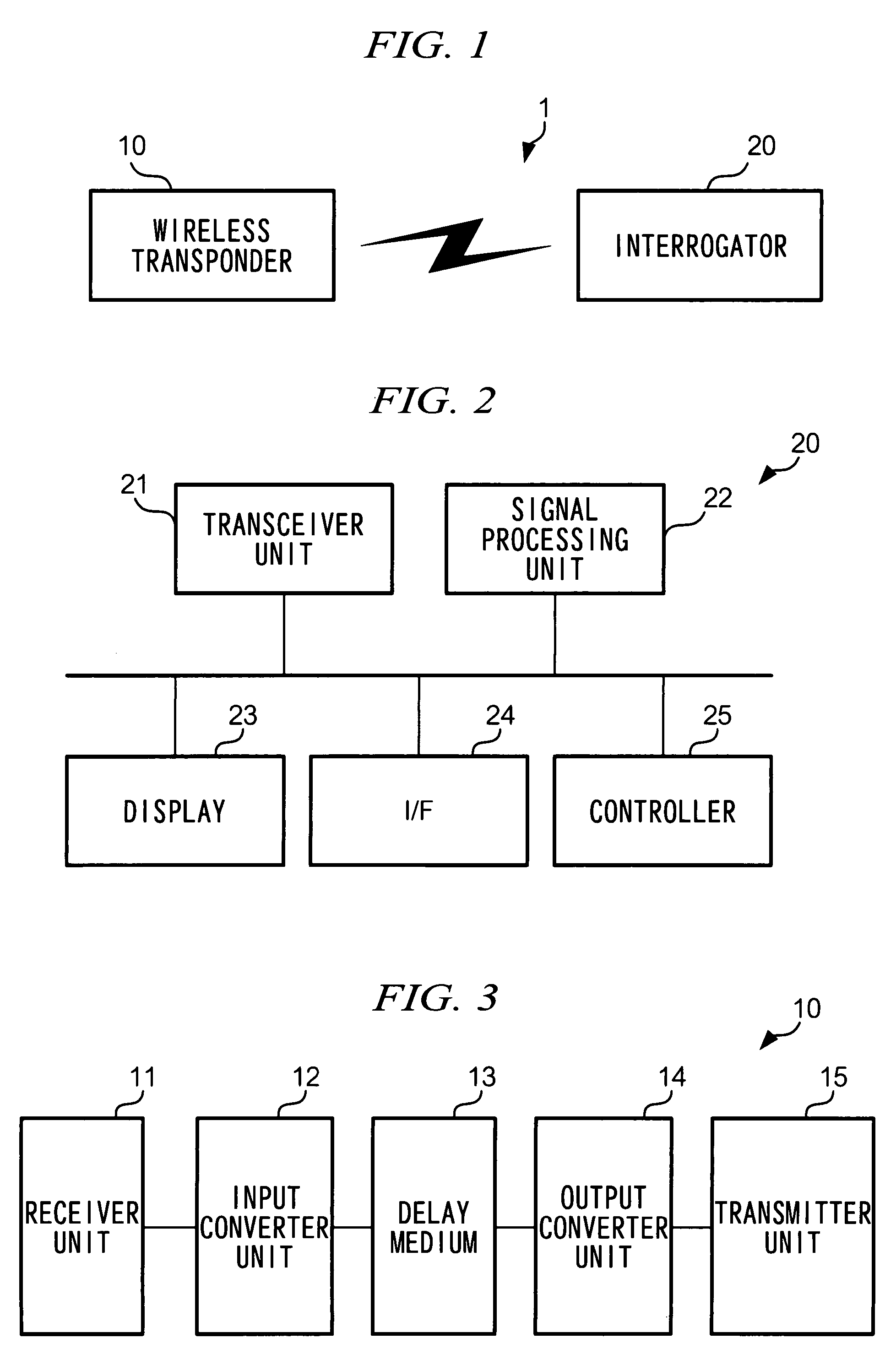
[0064]A receiver unit 102 has a coil antenna 103 and a matching circuit 104. A transmitter unit 105 has a coil antenna 106 and a matching circuit 107. The receiver unit 102 and the transmitter unit 105 are respectively formed on concave carriers 108 and 109.

[0065]An input converter 111 has a piezoelectric element 112 for converting an electric signal into an acoustic wave, and a substrate 113 for holding the pi...

second embodiment

[0074

[0075]FIG. 10A is a sectional view showing a device structure of a wireless transponder 200a according to the second embodiment of the invention. FIG. 6B is a sectional view showing a device structure of a wireless transponder 200b also according to the embodiment. The structures of the wireless transponders 200a and 200b are the same with the exception that delay media (delay media 201a and 201b) have different thicknesses. Suffixes a and b for reference numerals will be omitted from the following description where related members need not particularly be distinguished from each other by use of such suffixes.

[0076]Further, the wireless transponder 200 is manufactured in the same structure and method as the wireless transponder 100 according to the first embodiment except for the differences as follows. A material for the delay medium 201 and a thickness of the material are different. Matching circuits 204 and 207 are matched with a frequency of 130 kHz. Description of features...

third embodiment

[0079

[0080]FIG 11A is a sectional view showing a device structure of a wireless transponder 300a according to the third embodiment of the invention. FIG. 11B is a sectional view showing a device structure of the wireless transponder 300b according to the embodiment. The wireless transponders 300a and 300b have the same structure except that delay media (delay media 301a and 301b) have different thicknesses. Suffixes a and b which should be added to reference numerals will be omitted from the following description where related members need not particularly be distinguished from each other by the suffixes.

[0081]The following description will be primarily made with regard to such parts that differ from the wireless transponder 100 according to the first embodiment. In the wireless transponder 300, the same components as those in the wireless transponder 100 will be denoted by replacing the hundreds digit of the same reference symbols with 3. For example, a reference symbol 317 in FIGS...


PUM


Abstract

The present invention provides a wireless transponder comprising: a receiver unit that receives an electromagnetic input signal; an input converter unit that converts into an acoustic wave the electromagnetic input signal received by the receiver unit; a delay unit provided in a direction in which an acoustic wave generated by the input converter unit propagates; an output converter unit that converts into an electromagnetic output signal the acoustic wave which has propagated inside the delay unit; and a transmitter unit that transmits wirelessly the electromagnetic output signal generated by the output converter unit.

Description

BACKGROUND[0001]1. Technical Field[0002]The present invention relates to a wireless transponder and a wireless response method for transmitting / receiving a signal to / from an interrogator, and particularly to a wireless transponder capable of communication in a high-noise environment without a specific energy source, and an image forming device using the wireless transponder as a path sensor for a recording material.[0003]2. Related Art[0004]Various sensors have been developed with a view to measuring physical and chemical characteristics, and the like. In most such sensors, output signals vary depending on physical and chemical characteristics of the targets to be measured, and also the environment. Information such as physical and chemical characteristics concerning targets to be measured and the like is obtained by processing signals that are output as a result of measurement. The sensors are provided separately from a device (hereinafter an “interrogator”) for processing output s...

Claims


Application Information

Patent Timeline
Patent Type & Authority Patents(United States)
IPC IPC(8): H04Q5/22
CPCG01D21/00
Inventor WATANABE, MASAO
Owner FUJIFILM BUSINESS INNOVATION CORP
Why Eureka
Try Eureka