Power supply device and vehicle including the same

A power supply device and battery technology, applied in electric vehicles, vehicle components, circuits, etc., to achieve high reliability, prevent condensation, and eliminate gaps

Inactive Publication Date: 2013-01-02
SANYO ELECTRIC CO LTD
View PDF5 Cites 63 Cited by
  • Summary
  • Abstract
  • Description
  • Claims
  • Application Information

AI Technical Summary

Problems solved by technology

[0012] The present invention proposes to solve such existing problems

Method used


Image

  • Power supply device and vehicle including the same
  • Power supply device and vehicle including the same
  • Power supply device and vehicle including the same

Examples


Embodiment 1

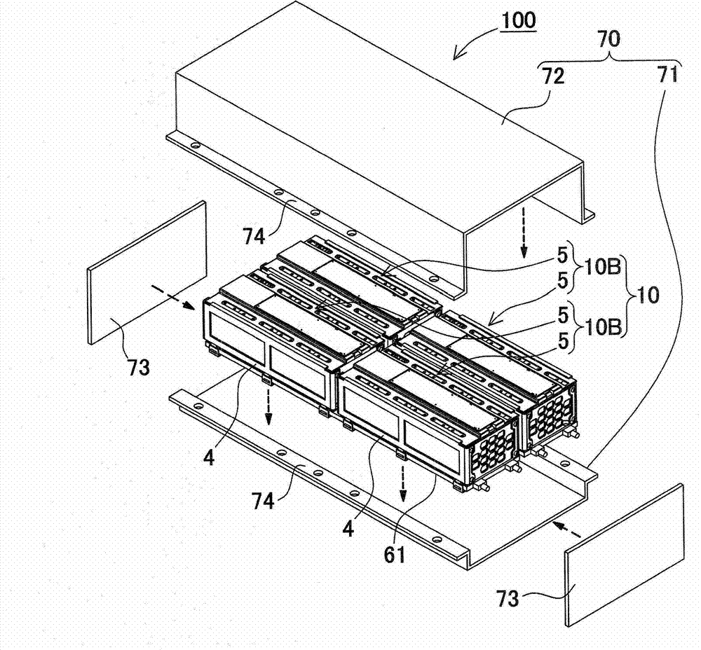
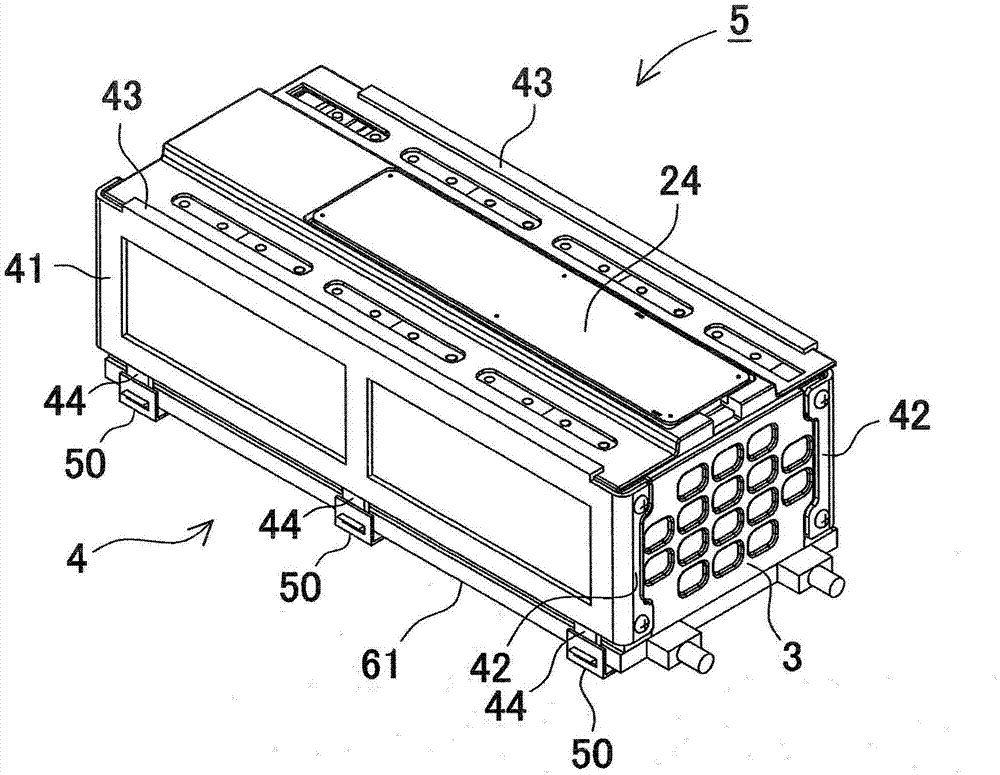
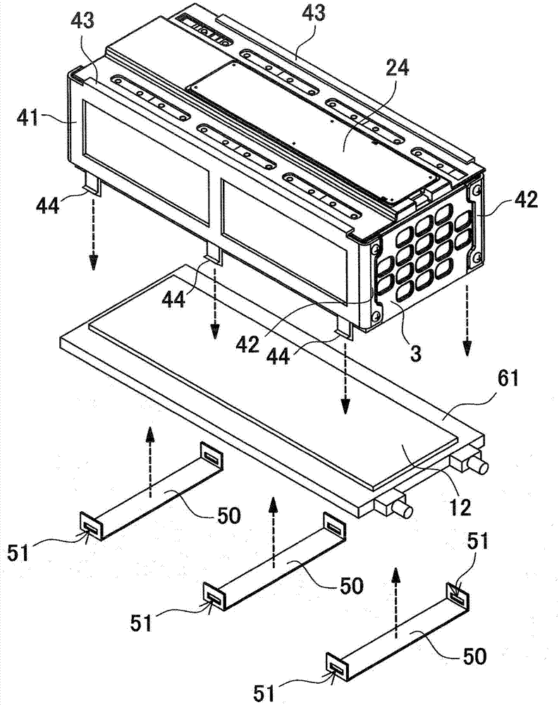
[0120] exist Figure 1 to Figure 13 Here, an example in which the power supply device 100 according to Embodiment 1 of the present invention is applied to a vehicle-mounted power supply device will be described. In the above figure, figure 1 is an exploded perspective view of the power supply device 100, figure 2 yes means figure 1 A perspective view of the battery stack 5, image 3 From figure 2 An exploded perspective view of the battery stack 5 with the cooling plate 61 removed, Figure 4 is viewed from obliquely below figure 2 The perspective view obtained from the battery stack 5, Figure 5 yes figure 2 An exploded perspective view of the battery stack 5 of Image 6 yes Figure 5 An exploded perspective view of the battery stack 5 of Figure 7 is a sectional view showing a power supply device according to a modified example, Figure 8 is a schematic cross-sectional view showing an example in which a water-absorbing sheet is disposed between the battery st...

Embodiment 2

[0163] As described above, by covering the case and the cooling plate and closing the battery stack 5 in an airtight state, circulation of air is blocked to avoid condensation of moisture in the air. In addition, not only the surface of the cover case can be formed into a waterproof structure, but also the surface of the battery stack can be covered with a filling layer to form a structure that fills the gap, thereby protecting the surface of the battery stack surrounded by the cover case from Affected by water droplets, etc. exist Figure 14 An example of a power supply device adopting such a structure is shown as Embodiment 2 in a cross-sectional view of . In the power supply device shown in the figure, a filling layer 18 is disposed between the battery stack 5 and the cover case 16 . That is, by filling the gap between the battery stack 5 and the cover case 16 with a filling material to form the filling layer 18 , it is possible to prevent moisture condensation in the air...

Embodiment 3

[0175] In addition, a part of the waterproof sheet 19 may be removed so that the thermally conductive sheet 12 is in direct contact with the battery stack 5 . exist Figure 15 Such an example is shown in Embodiment 3. The battery laminated body 5 shown in the figure is formed from Figure 17 In the state shown, the waterproof sheet 19 covering the bottom surface of the battery stack 5 is removed. The bottom surface of the battery stack 5 is exposed at the portion where the waterproof sheet 19 is removed, so the thermally conductive sheet 12 is pressed against this surface so that the battery stack 5 and the thermally conductive sheet 12 are directly in close contact with each other, thereby reducing thermal resistance and improving cooling performance through cooling. The plate 61 performs heat dissipation for heat dissipation. In addition, after curing of the filler, the surface of the battery stack 5 is already sealed except for the exposed portion, so the waterproof stru...


PUM


Abstract

The invention provides a power supply device and a vehicle including the same, the condition of moisture condensation at the surface of a battery unit can be prevented, and thermal coupling of the battery unit and a cooling plate (61) can also be maintained. The power supply device includes a battery assembly (5), a box-shaped cover case (16), a cooling plate (61), and a waterproof sheet (19). The battery assembly (5) includes rectangular battery cells (1) arranged side by side. Exterior surfaces of the battery assembly (5) are covered with surfaces of the cover case (16) other than the local of one surface. The cooling plate (61) is thermally coupled to one surface of the battery assembly (5). Coolant flows through the cooling plate (61) whereby transferring heat from the battery assembly (5) to the coolant. The waterproof sheet (19) covers the one surface of the battery assembly (5). Gaps between the battery assembly (5) and the cover case (16) are filled with a sealing material so that a sealing layer (18) is interposed between them. The waterproof sheet (19) is fastened by the sealing layer (18).

Description

technical field [0001] The present invention relates to a large-current power supply device mainly used for power supply for driving a motor of a vehicle such as a hybrid vehicle or an electric vehicle, or for storage of electricity in a household or factory, and a vehicle equipped with such a power supply device. Background technique [0002] Power supply devices with increased output, such as battery packs for vehicles, are required. In such a power supply device, a plurality of battery cells are connected in series to increase the output voltage and increase the output power. The battery cell generates heat when charged and discharged with a large current. In particular, as the number of battery cells used increases, the amount of heat generated also increases. Therefore, there is a demand for a heat dissipation mechanism that efficiently conducts heat from the battery cells to dissipate it. As such a heat dissipation mechanism, in addition to the air-cooling method in...

Claims


Application Information

Patent Timeline
Patent Type & Authority Applications(China)
IPC IPC(8): H01M2/10H01M10/50B60L11/18H01M10/60H01M10/613H01M10/625H01M10/627H01M10/653H01M10/6556H01M10/6567H01M50/209H01M50/262H01M50/271H01M50/289
CPCY02E60/12H01M10/5004H01M10/5075H01M10/5057H01M2/1094H01M2/1072H01M10/5016H01M10/5032H01M10/5053H01M10/625H01M10/647H01M10/6556H01M10/6567H01M10/6554H01M10/613Y02E60/10H01M50/24H01M50/209H01M50/289H01M50/262H01M50/271
Inventor 桥本裕之土屋正树浅井康广濑户高志笼谷贵英
Owner SANYO ELECTRIC CO LTD
Why Eureka
Try Eureka