Evaporator

a technology of evaporator and evaporator chamber, which is applied in the direction of indirect heat exchangers, refrigeration components, light and heating apparatus, etc., can solve the problems of increased defect rate, decreased assembly productivity, increased fabrication costs, etc., and achieves the effect of enhancing the heat radiating state, reducing the pressure loss of air, and facilitating the discharge of condensation water

Inactive Publication Date: 2005-08-11
MODINE KOREA
View PDF10 Cites 63 Cited by
  • Summary
  • Abstract
  • Description
  • Claims
  • Application Information

AI Technical Summary

Benefits of technology

[0014] It is still further another object of the present invention to provide an evaporator which is capable of enhancing a heat radiating state and decreasing a pressure loss of air by forming a connection portion between a front tube portion and a rear tube portion.
[0015] It is still further another object of the present invention to provide an evaporator which is capable of implementing an easier discharge of a condensation water through a tube gathered from a surrounding of the tube and preventing a condensation water from being gathered in the header unit and a wrinkle portion provided between the tubes from being transformed, by improving the shapes of both side ends of the tube and the shape of the header plate.
[0016] It is still further another object of the present invention to provide an evaporator which is capable of increasing a cooling effect by forming an evaporator using the upper and lower header units and tubes and forming a path structure of a refrigerant based on a certain division ratio.
[0017] To achieve the above objects, in an evaporator including upper and lower header units which each have a two-row refrigerant flow path, a plurality of tubes which connect the upper and lower header units and are formed of an aluminum material and are arranged in two rows in front and rear sides with respect to the flowing direction of air and are stack-arranged in parallel in the direction orthogonal to the flowing direction of air for flowing a refrigerant therethrough, and a wrinkle fin which is provided between the neighboring tubes for enhancing a heat transfer area of air passing through the tubes and is formed of an aluminum material, there is provided the header unit which includes a tank member having a U-shaped cross section and a vertical groove in an inner center portion in a longitudinal direction, and a groove formed in an inner surface of both side ends in a longitudinal direction; a partition member which divides an inner space of the tank member in a width-wise direction by inserting a lower side end into the vertical groove of the tank member; a header plate which is engaged between the grooves of both sides of the tank member and covers an opened portion of the tank member for sealing and has a plurality of tube holes for inserting the tubes; an intermediate baffle which is formed based on the shape of the inner portion of the tank member and partitions the inner space of the tank member; and a finishing baffle which is formed based on the shape of the inner portion of the tank member and covers the inner space for sealing when the same is assembled to both side ends of the tank member.

Problems solved by technology

Therefore, the assembling productivity is decreased compared to the materials extruded, and the fabrication cost is increased.
A defect rate is increased due to the transformation by the temporary welding operation.
In the above construction, a condensation water produced during a heat exchange is not easily separated, namely flows in a lateral side, thus decreasing a heat exchange efficiency.

Method used


Image

  • Evaporator
  • Evaporator
  • Evaporator

Examples


embodiment 1

[0090] As shown in FIG. 15, the embodiment 1 of the present invention is implemented based on the above described elements as a basic type.

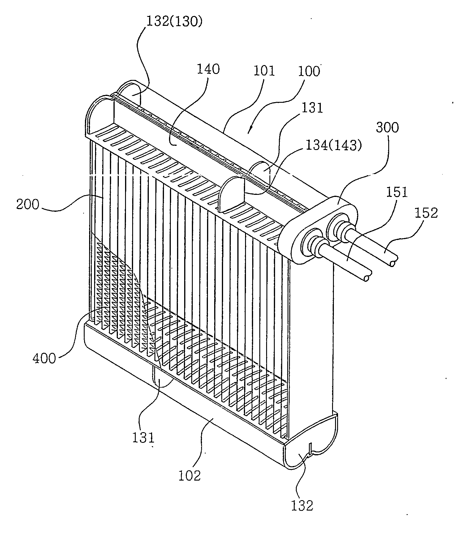
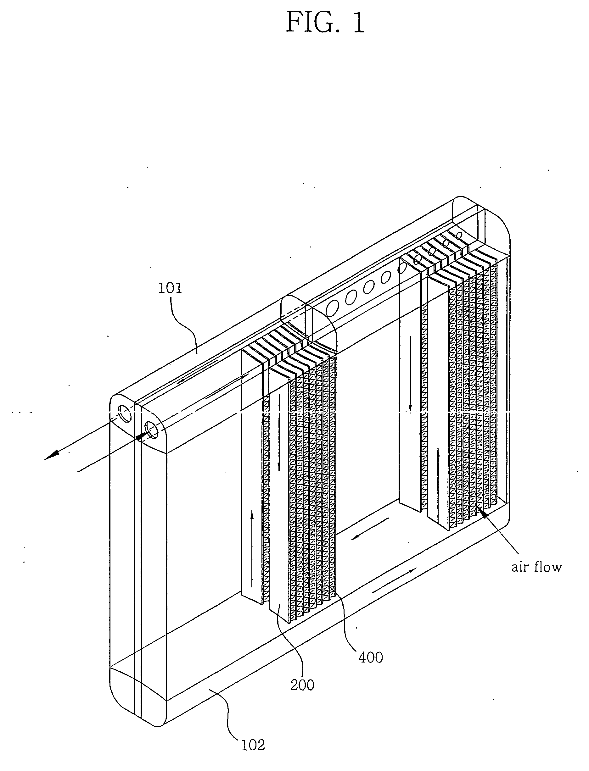
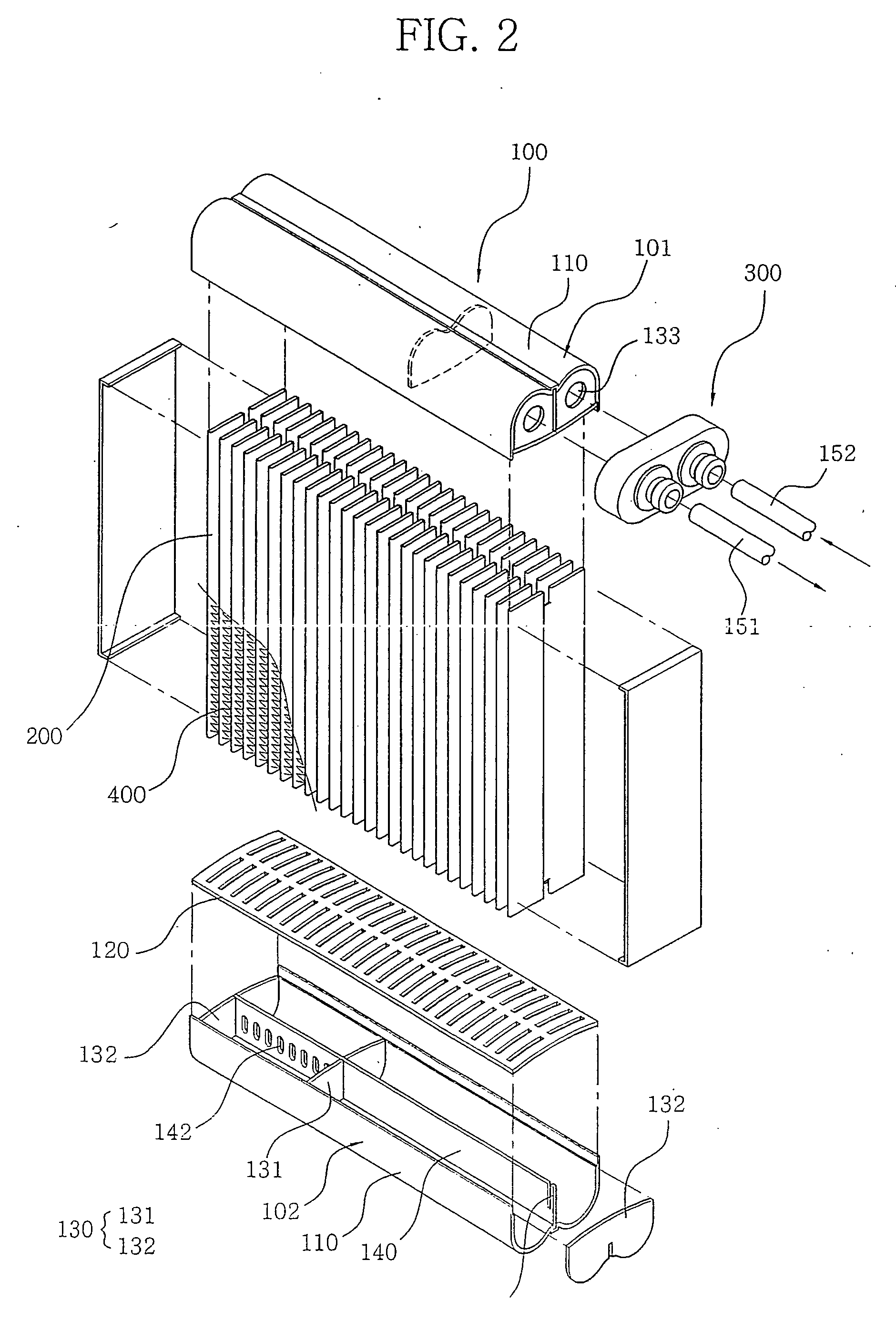
[0091] Namely, there are provided upper and lower header units 101 and 102, a two-row tube 200 connecting the header units, and a wrinkle fin 400 provided between the tubes. As described above, the upper side header unit 101 connects a refrigerant inlet pipe 151 and a refrigerant outlet pipe 152 using the adaptor 300 in one side finishing baffle 132.

[0092] The interior of the upper header unit 101 is divided by the partition member 140 which is assembled in the longitudinal direction and divides the width-wise portion, and the intermediate baffle 131 which is engaged with the partition member 140 and the cut groove 143 and divides the left and right lengths at about ⅓ distance of the right side in the drawing.

[0093] The interior of the lower side header unit 102 is divided by the partition member 140 which is assembled in the longitudinal dire...

embodiment 2

[0101]FIG. 17 is a view illustrating the paths structure according to the second embodiment of the present invention.

[0102] As shown in FIG. 17, the adaptor 300 is connected to an intermediate portion of the upper header unit 101. There are provided upper and lower header units 101 and 102, a two-row tube 200 connecting the header units, and a wrinkle fin 400 provided between the tubes. The upper and lower header units 101 and 102 are sealed using the finishing baffle 132.

[0103] The interior of the upper header unit 101 is divided by a partition member 140 which is assembled in the longitudinal direction and divides the front and rear width portions, and an intermediate baffle 131 which is assembled to be engaged with the partition member 140 and the cut groove 143 and divides the left side portion by ½ or divides the right side portion by ½. In the interior of the lower header unit 102, there is only the partition member 140 which is assembled in the longitudinal direction and di...


PUM


Abstract

The present invention relates to an evaporator for an air conditioner of a vehicle, and the major object of the present invention is to provide the evaporator which is capable of decreasing the whole dimension of an evaporator and enhancing a heat exchange performance. To achieve the above objects, an evaporator includes an upper and lower header units comprising a tank member, a partition member, a header plate, an intermediate baffle, a finishing baffle; and a plurality of tubes comprising a front tube portion, a rear tube portion, a connection tube portion; and a wrinkle fin.

Description

TECHNICAL FIELD [0001] The present invention relates to an evaporator for an air conditioner of a vehicle having a plurality of tube rows, and in particular to an evaporator which is capable of decreasing the whole dimension and maximizing a heat exchange efficiency in such a manner that there is provided a two-row tube structure connected between upper and lower header units of an evaporator, and a header unit, tube and wrinkle portion are improved. BACKGROUND ART [0002] Generally, as shown in FIG. 1, an evaporator having a plurality of tube rows includes header units 101 and 102 provided in upper and lower sides, respectively, tubes 200 provided in two rows, one row in a front side and another row in a rear side, with respect to a flow of air, and a wrinkle fin 400 provided between the tubes. In the above structure, a heat exchange is implemented between a fluid flowing therein and air flowing between the tubes. [0003] In the improvement of the thusly constituted evaporator, it is...

Claims


Application Information

Patent Timeline
Patent Type & Authority Applications(United States)
IPC IPC(8): F28F9/013F28D1/053F28F9/02F28F9/04
CPCF28D1/05391F28D2021/0085F28F9/0253F28F9/0224F28F9/0246F28F9/0207F28F9/013
Inventor CHO, JAE-HEONKIM, JAE-HOON
Owner MODINE KOREA
Why Eureka
Try Eureka