
An electric tricycle for transportation

A technology of electric tricycles and carriages, which is applied in the direction of motor vehicles, transportation and packaging, vehicles with elevated loading platforms, etc., to achieve the effect of reducing work intensity and ensuring safety

Active Publication Date: 2022-01-18
丰县通亚电子科技有限公司
View PDF7 Cites 0 Cited by
  • Summary
  • Abstract
  • Description
  • Claims
  • Application Information

AI Technical Summary

Problems solved by technology

[0004] But in the prior art, when using the electric tricycle to carry the goods, because the compartment of the electric tricycle has a certain distance from the ground, when loading and unloading goods, it is basically all manually carried, and for carrying the patient or the disabled. Personnel assistance to get on and off, especially for disabled people in wheelchairs, it is necessary to separate wheelchairs from disabled people to ensure the safety of getting on and off the bus

Method used


Image

  • An electric tricycle for transportation
  • An electric tricycle for transportation
  • An electric tricycle for transportation

Examples


Embodiment 1

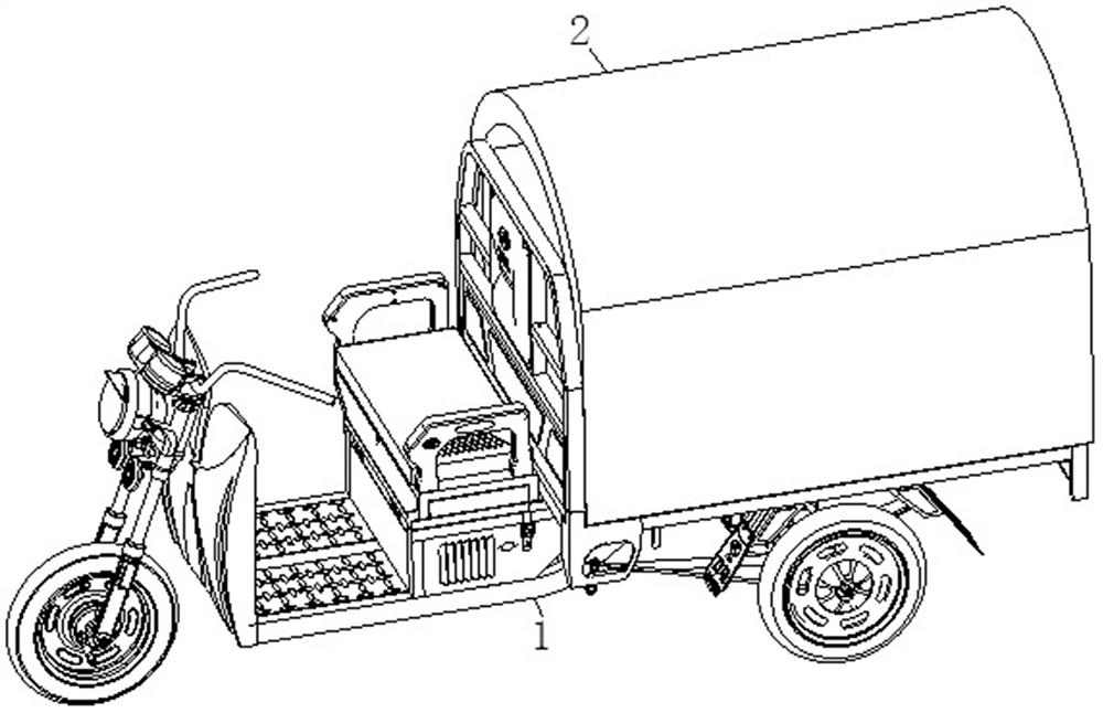
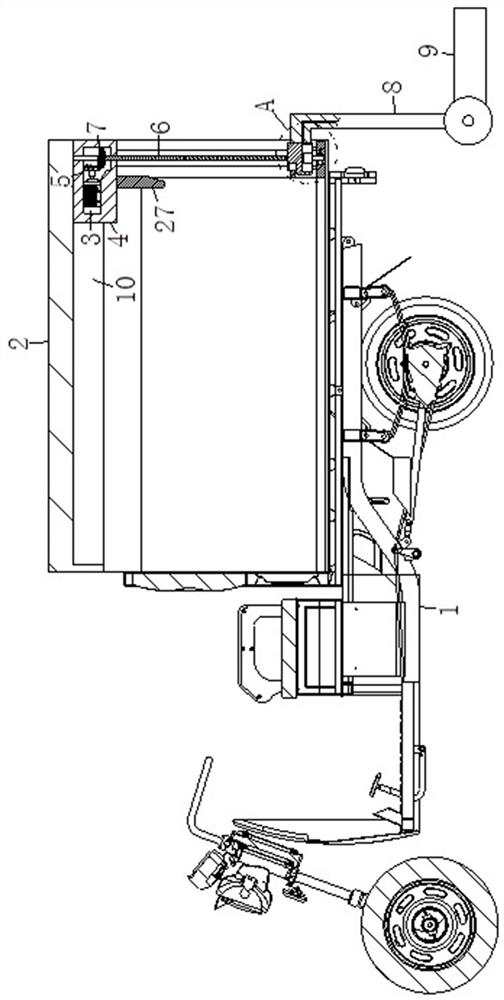
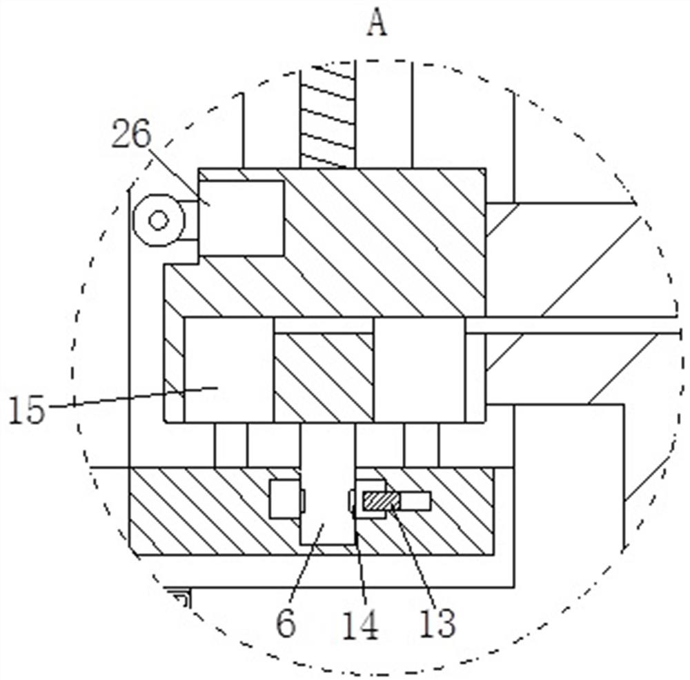
[0032] see Figure 1-Figure 6 As shown, an electric tricycle used for transportation includes a car body 1, a compartment 2 and a motor 3; the top of the car body 1 is fixedly connected with a compartment 2; the interior of the compartment 2 is provided with a connecting block near the rear of the vehicle 4; the inside of the connection block 4 is fixedly connected with a motor 3 near the top of the connection block 4; the output shaft of the motor 3 is fixedly connected with a first bevel gear 5; the surface of the connection block 4 is connected with a screw rod in rotation 6; the surface of the screw mandrel 6 is fixedly connected with the second bevel gear 7 near the top position of the screw mandrel 6, and the second bevel gear 7 is engaged with the first bevel gear 5; the nut of the screw mandrel 6 The surface is fixedly connected with a connecting rod 8; the surface of the connecting rod 8 is close to the bottom position of the connecting rod 8 and is connected with a p...

Embodiment 2

[0041] see Figure 7 and Figure 8 As shown, the positions between the two ball grooves 28 are equipped with mounting grooves; the inside of the mounting grooves are provided with balls 34; during work, by setting the balls 34 on the surface of the shaped plate 25, when the shaped plate When 25 is concave, the adjacent balls 34 will be squeezed together. At this time, the balls 34 in the squeezed state will not rotate directly to ensure the stability of the goods and personnel at this position. When in a flat state, the balls 34 stop squeezing each other, and the goods can be easily unloaded by pushing them.

[0042] The groove bottom of the safety groove 21 is fixedly connected with the second air bag 35 arranged evenly; Both are connected to each other through pipelines; the inside of the control groove 36 is fixedly connected with a telescopic bag 37; the top surface of the telescopic bag 37 is fixedly connected with a control block 38; the top surface of the control bloc...


PUM


Abstract

The invention relates to the field of electric vehicles, in particular to an electric tricycle for transportation; it includes a car body, a carriage and a motor; the top of the car body is fixedly connected with a carriage; The inside of the block is fixedly connected with a motor; the output shaft of the motor is fixedly connected with a first bevel gear; the surface of the connecting block is connected with a screw rod for rotation; the surface of the screw rod near the top of the screw rod is fixedly connected with a first Two bevel gears; the surface of the nut of the screw mandrel is fixedly connected with a connecting rod; the surface of the connecting rod near the bottom of the connecting rod is rotatably connected with a pressure plate; through the present invention, the tail of the electric tricycle is increased with an automatic lifting function part , which is convenient for workers to load and unload goods and passengers to ride, reducing the work intensity of staff loading and unloading goods. At the same time, for special people, the pressure plate can be directly up and down automatically, without more auxiliary personnel, which is convenient for special personnel. Travel short distances quickly.

Description

technical field [0001] The invention relates to the field of electric vehicles, in particular to an electric tricycle used for transportation. Background technique [0002] As a means of transportation driven by electric motors, electric tricycles play an important role in short-distance express freight and family travel. [0003] According to CN110065572A electric tricycle compartment, the technical scheme of the invention is provided with a number of limit plates on the box plate, which can limit the positions and angles of several limit plates under the cooperation of the connecting road, connecting column and connecting block, and then can according to the actual situation. It is necessary to adjust the position of the limiting plate to adapt to the transportation of different items. Compared with the prior art, the structure is reasonable, and it can be adjusted freely without the cover plate structure, which improves the overall adaptability while reducing the cost. ...

Claims


Application Information

Patent Timeline
Patent Type & Authority Patents(China)
IPC IPC(8): B62K5/027B62K7/04B60P1/44
CPCB62K5/027B62K7/04B60P1/44
Inventor 张红云
Owner 丰县通亚电子科技有限公司
Learn More