Tunnel portal flood control emergency equipment

A technology for first aid equipment and tunnel entrances, applied in mining equipment, mining equipment, earthwork drilling and mining, etc. It can solve problems such as inconvenient use, inability to evacuate people in the tunnel in time, inconvenience in travel, etc., and achieve the best waterproof effect

Active Publication Date: 2021-11-09
CCCC TUNNEL ENG
View PDF5 Cites 0 Cited by
  • Summary
  • Abstract
  • Description
  • Claims
  • Application Information

AI Technical Summary

Problems solved by technology

[0002] Although the tunnel entrance is generally equipped with waterproof facilities, when there is heavy rain, there is still a large amount of rainwater flowing down from the top of the mountain and pouring into the tunnel entrance, or the tunnel cave is located in a relatively low-lying area, resulting in water accumulation in the tunnel, vehicles stalling, and people being trapped. Trapped in the tunnel, it brings inconvenience to people's travel, and sometimes the speed of accumulated water will cause the people in the tunnel to be unable to evacuate in time, which poses a greater threat to the safety of people's lives
[0003] The existing waterproof methods generally use sandbags to block or block through baffles at zero time, which is inconvenient to use, or the rescuers use water pumps to pump water into the tunnel, but it takes time for the rescuers to rush to the tunnel, so there is an urgent need for an automatic detection method. Tunnel water level and rapid and efficient waterproofing of tunnel entrance flood control first aid equipment

Method used


Image

  • Tunnel portal flood control emergency equipment
  • Tunnel portal flood control emergency equipment
  • Tunnel portal flood control emergency equipment

Examples


Embodiment Construction

[0030] The following are specific embodiments of the present invention and in conjunction with the accompanying drawings, the technical solutions of the present invention are further described, but the present invention is not limited to these embodiments.

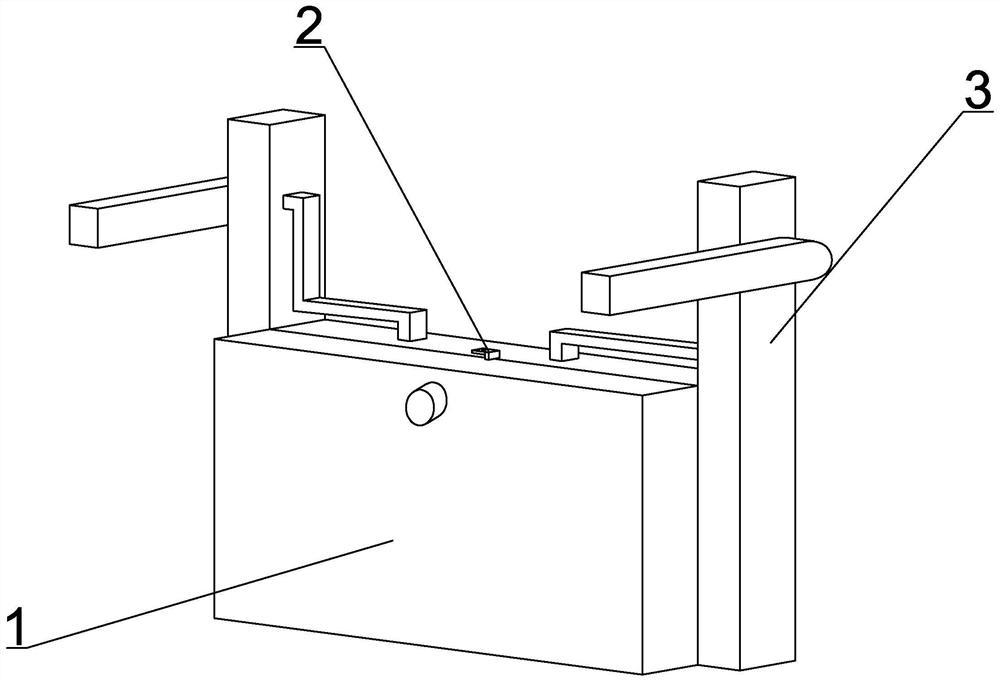
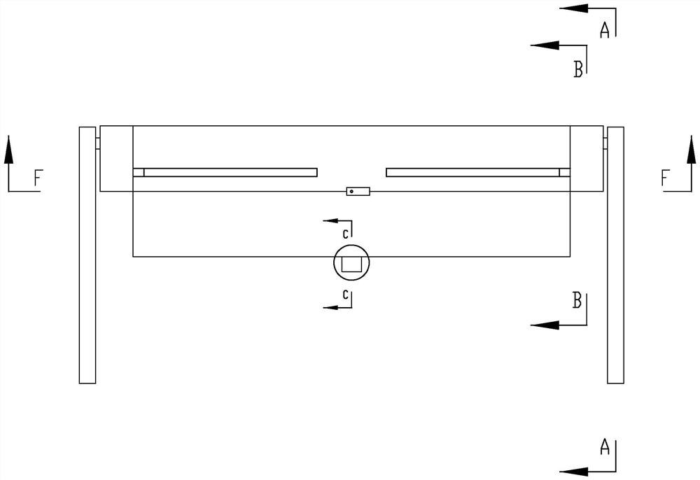
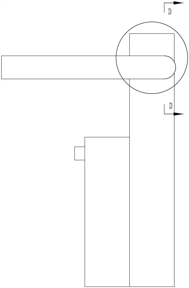
[0031] combine Figure 1-10 , a first-aid equipment for flood control at a tunnel entrance, comprising a water blocking part 1, the inflatable part 1 is provided with an inflatable chamber 102 placed on the ground, one side of the inflatable chamber 102 is provided with an airbag 101, and a plurality of inflatable chambers are provided on the connection surface between the inflatable chamber 102 and the airbag 101 The hole 103, the connection surface between the inflatable chamber 102 and the airbag 101 is fixed with a switch valve body 105, and the two sides of the inflatable chamber 102 perpendicular to the direction facing the airbag 101 are respectively fixed with a water pump 116, and the water outlet 104 of the water ...


PUM


Abstract

The invention belongs to the field of tunnel portal flood control first-aid equipment, and particularly relates to tunnel portal flood control emergency equipment. The equipment comprises a water blocking component, a water level detection component and an air bag supporting component, wherein an inflation component is provided with an inflation chamber placed on the ground, an air bag is arranged on one side face of the inflation chamber, a plurality of inflation holes are formed in the connecting face of the inflation chamber and the air bag, a switch valve body is fixedly arranged on the connecting face of the inflation chamber and the air bag, water pumps are fixedly arranged on the two side faces, perpendicular to the direction facing the air bag, of the inflation chamber respectively, water outlets of the water pumps communicate with the interior of the air bag, a one-way valve body is fixedly arranged on the upper portion of the side, away from the inflation chamber, of the outer portion of the air bag, a ball is slidably arranged in the one-way valve body in a sleeved mode, the ball is connected with the one-way valve body through a one-way spring, a gas ignition coil is arranged in the inflation chamber, the water level detection component is arranged in the inflation chamber and is responsible for detecting the rising speed and height of the water level and triggering the ignition coil to enable the air inflation chamber to work, and the air bag supporting component is arranged in the inflation chamber and is used for supporting and guiding the inflated air bag.

Description

technical field [0001] The invention belongs to the field of first-aid equipment for flood control at tunnel entrances, in particular to first-aid equipment for flood control at tunnel entrances. Background technique [0002] Although the tunnel entrance is generally equipped with waterproof facilities, when there is heavy rain, there is still a large amount of rainwater flowing down from the top of the mountain and pouring into the tunnel entrance, or the tunnel cave is located in a relatively low-lying area, resulting in water accumulation in the tunnel, vehicles stalling, and people being trapped. Being trapped in the tunnel brings inconvenience to people's travel, and sometimes the speed of accumulated water will cause the people in the tunnel to be unable to evacuate in time, which poses a greater threat to the safety of people's lives. [0003] The existing waterproof methods generally use sandbags to block or block through baffles at zero time, which is inconvenient t...

Claims


Application Information

Patent Timeline
Patent Type & Authority Applications(China)
IPC IPC(8): E21F17/107
CPCE21F17/107
Inventor 李樊艳
Owner CCCC TUNNEL ENG
Why Eureka
Try Eureka