Mini-tiller gear shifting transmission assembly and mini-tiller

A micro-tiller and assembly technology, applied in the field of micro-tillers, can solve problems such as potential safety hazards, increased reverse gear speed, and loss of the best time to get out of trouble

Active Publication Date: 2022-01-25
LONCIN MOTOR +2
View PDF7 Cites 0 Cited by
  • Summary
  • Abstract
  • Description
  • Claims
  • Application Information

AI Technical Summary

Problems solved by technology

The disadvantage of this structure is that in order to take into account the engagement of the reverse drive gear with other forward driven gears, the rotational speeds of the two forward gears are relatively close, which is difficult to meet the requirements of daily use, and because the reverse drive gear must participate in the engagement of the fast gear teeth , but also participate in the meshing of the reverse gear. If the speed of the fast gear is increased, the speed of the reverse gear will also be increased, which cannot meet the requirements of regulations and has potential safety hazards.
Moreover, when the tiller is stuck in paddy fields or silt, it is impossible to quickly put the tiller into the reverse gear, withdraw the tiller from the mud, and lose the best time to get out of trouble

Method used


Image

  • Mini-tiller gear shifting transmission assembly and mini-tiller
  • Mini-tiller gear shifting transmission assembly and mini-tiller
  • Mini-tiller gear shifting transmission assembly and mini-tiller

Examples


Embodiment Construction

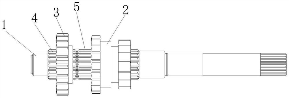
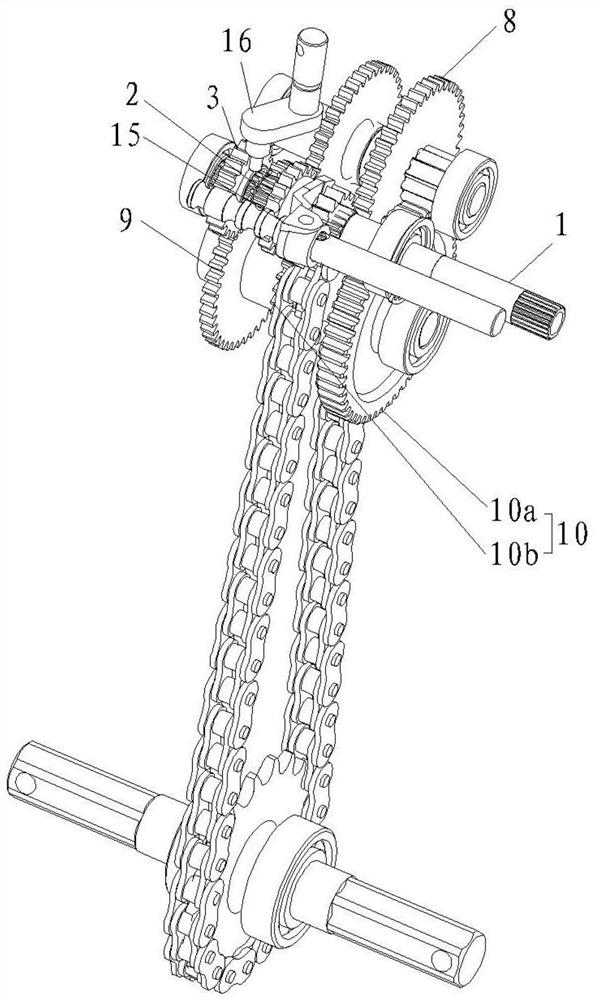
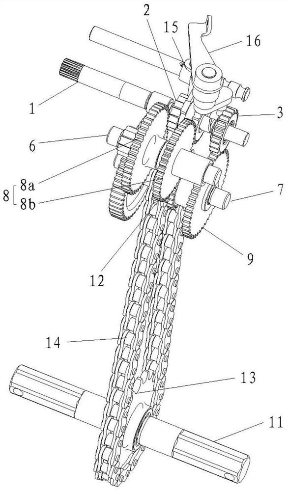
[0019] This embodiment provides a micro tillage machine replacement assembly, including a main shaft 1, a forward gear driving gear 2 and a reverse gear driving gear 3, the forward gear driving gear 2 is rotatably mounted on the main shaft, and the reverse gear driving gear 3 Installed on the main shaft in a transmission fit and axially slidable manner, the reverse driving gear 3 has at least two transmission states when sliding axially along the main shaft:

[0020] State 1: the reverse driving gear 3 is disconnected from the forward driving gear 2, and the reverse driving gear 3 is used to mesh with the reverse transmission structure to transmit power to the output shaft to drive the output shaft to reverse;

[0021] State 2: Reverse gear driving gear 3 is in transmission cooperation with forward gear driving gear 2, and the reverse gear driving gear is separated from the reverse gear transmission structure, and the power is transmitted to the output shaft through the forward...


PUM


Abstract

The invention provides a mini-tiller gear shifting transmission assembly. The mini-tiller gear shifting transmission assembly comprises a main shaft, an intermediate shaft, an output driven shaft, a forward-gear intermediate gear, a reverse-gear driven gear, a forward-gear driven gear, a forward-gear driving gear and a reverse-gear driving gear. The reverse-gear driving gear has at least two transmission states when sliding in the axial direction of the main shaft. In the first state, the reverse-gear driving gear is engaged with the reverse-gear driven gear to transmit power to the output driven shaft and drive the output driven shaft to rotate reversely. In the second state, the reverse-gear driving gear is in transmission fit with the forward-gear driving gear, and the forward-gear driving gear is engaged with the forward-gear intermediate gear to transmit power to the output driven shaft and drive the output driven shaft to rotate forwards. The invention further provides the mini-tiller gear shifting transmission assembly and a mini-tiller. The mini-tiller gear shifting transmission assembly is applied to the mini-tiller. According to the mini-tiller gear shifting transmission assembly, the reverse gear can be quickly realized at any forward gear, so that the mini-tiller can get out of the trouble in time, and the situation that it is difficult to get out of the trouble due to time delay caused by reverse gear engagement is avoided.

Description

technical field [0001] The invention belongs to the technical field of tillage machines, and in particular relates to a shifting transmission assembly of a tiller and a tiller. Background technique [0002] The reverse drive gear of the existing micro tillage machine is usually a double gear, and the reverse drive gear doubles as the drive wheel of the forward gear. At the movable tooth, it meshes with the driven tooth of the reverse gear to realize the reverse gear. The disadvantage of this structure is that in order to take into account the engagement of the reverse drive gear with other forward driven gears, the rotational speeds of the two forward gears are relatively close, which is difficult to meet the requirements of daily use, and because the reverse drive gear must participate in the engagement of the fast gear teeth , but also to participate in the engagement of the reverse gear, if the speed of the fast gear is increased, the speed of the reverse gear will also ...

Claims


Application Information

Patent Timeline
Patent Type & Authority Applications(China)
IPC IPC(8): F16H37/06F16H57/00F16H63/32F16D3/06A01B33/08
CPCF16H37/065F16H57/0025F16H57/0037F16H63/32F16D3/06A01B33/082
Inventor 喻诗品何道刚刘荣利许宝
Owner LONCIN MOTOR
Why Eureka
Try Eureka