A robot trapped detection method and robot

A robot and detection sensor technology, applied in the field of robots, can solve the problems of reducing user experience and the robot cannot perform operations according to instructions in a timely manner, so as to achieve the effect of improving user experience

Active Publication Date: 2021-05-14
PUPPY ELECTRONICS APPLIANCES INTERNET TECH (BEIJING) CO LTD
View PDF12 Cites 0 Cited by
  • Summary
  • Abstract
  • Description
  • Claims
  • Application Information

AI Technical Summary

Problems solved by technology

[0003] During the execution of some tasks (for example, the task is to clean the ground in different rooms), the robot needs to walk in the task execution site; moreover, the robot may be trapped by obstacles in the task execution site during the walking process, making the robot Unable to continue walking, resulting in the robot being unable to perform operations in a timely manner according to instructions, which reduces the user experience

Method used


Image

  • A robot trapped detection method and robot
  • A robot trapped detection method and robot

Examples


Embodiment 1

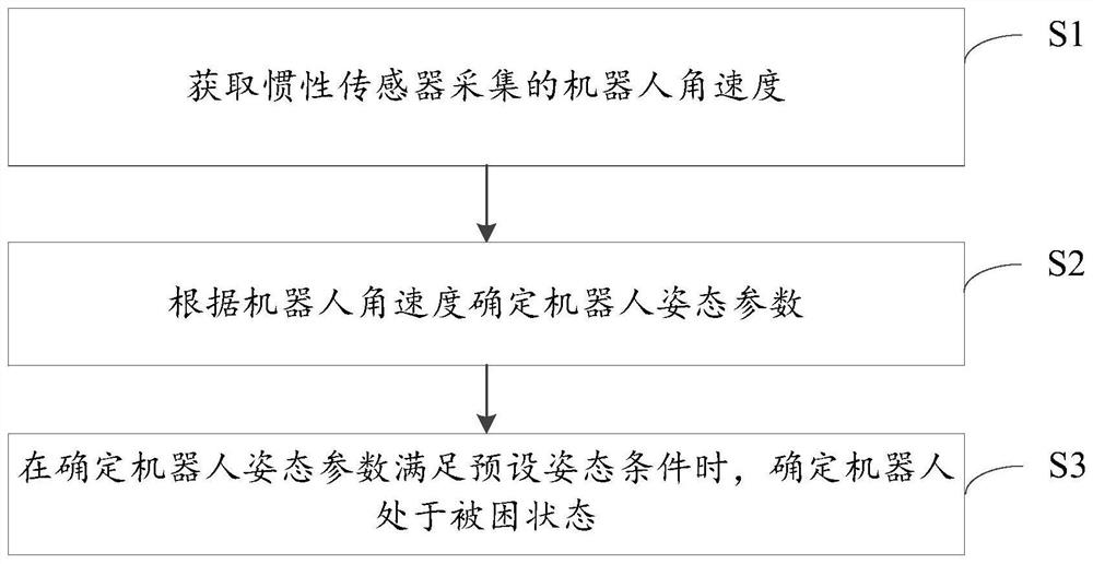
[0079] see figure 1 , which is a flow chart of a method for detecting a trapped robot provided in an embodiment of the present application.

[0080] The robot trapped detection method provided in the embodiment of this application includes S1-S3:

[0081] S1: Obtain the angular velocity of the robot collected by the inertial sensor.

[0082] Inertial sensors are used to detect and measure acceleration, tilt, shock, vibration, rotation, and multi-degree-of-freedom motion, and are important components for solving navigation, orientation, and motion carrier control; moreover, the embodiments of the present application do not limit inertial sensors, for example, inertial sensors It may include an accelerometer (or acceleration sensor) and / or an angular velocity sensor (gyro), may also include an inertial measurement unit (Inertial measurement unit, IMU), and may also include an attitude reference system (Attitude and heading reference system, AHRS).

[0083] The angular velocity...

Embodiment 2

[0114] In addition, because different moving wheels will be subjected to different pressures for a robot in an inclined state, the embodiment of the present application can determine the information of the degree of inclination of the robot according to the pressure on the moving wheels, so that the embodiment of the present application can determine the information of the degree of inclination of the robot based on the degree of inclination information to determine if the robot is trapped. Based on this, the embodiment of the present application also provides another implementation of the method for detecting a trapped robot. In this implementation, the method for detecting a trapped robot includes the following two steps in addition to the above steps:

[0115] Step 1: Obtain the wheel pressure collected by the wheel pressure detection sensor corresponding to the moving wheel.

[0116] The moving wheels are installed on the robot, and the moving wheels are used to realize th...

Embodiment 3

[0124] In addition, the embodiment of the present application may also determine whether the robot is trapped according to the height value of the robot from the ground. Based on this, the embodiment of the present application also provides another implementation of the method for detecting a trapped robot. In this implementation, the method for detecting a trapped robot may not only include the above steps, but also include: obtaining the distance of the robot from the cliff detection sensor. ground height value. At this time, S3 may specifically be: determining that the robot is in a trapped state when it is determined that the attitude parameters of the robot meet the preset attitude conditions and / or the height of the robot meets the preset ground clearance conditions.

[0125] The cliff detection sensor is used to collect the height value of the robot; moreover, the embodiment of the present application does not limit the number and installation position of the cliff dete...


PUM


Abstract

The present application discloses a robot trapped detection method and a robot. The method includes: after acquiring the angular velocity of the robot collected by an inertial sensor, determining the attitude parameters of the robot according to the angular velocity of the robot, so as to determine that the attitude parameters of the robot meet the preset Attitude condition, it is determined that the robot is in a trapped state. Among them, because the preset attitude conditions can accurately characterize the attitude parameters of the robot when it is in a trapped state, it can be accurately determined that the robot is in a trapped state when it is determined that the robot's attitude parameters meet the preset attitude conditions, so that it can be timely It is found that the robot is in a trapped state, so that the trapped robot can be released in a timely manner, so that the robot can continue to perform operations according to the instructions after being released, and the user experience is improved.

Description

technical field [0001] The present application relates to the technical field of robots, and in particular to a method for detecting a robot being trapped and a robot. Background technique [0002] With the development of intelligent technology, robots (for example, sweeping robots) have gradually attracted people's attention. Among them, the robot can perform various tasks (for example, sweeping the floor) according to the instructions triggered by the user. [0003] During the execution of some tasks (for example, the task is to clean the ground in different rooms), the robot needs to walk in the task execution site; moreover, the robot may be trapped by obstacles in the task execution site during the walking process, making the robot Unable to continue walking, the robot cannot perform operations according to the instructions in a timely manner, which reduces the user experience. Contents of the invention [0004] In order to solve the above technical problems existin...

Claims


Application Information

Patent Timeline
Patent Type & Authority Patents(China)
IPC IPC(8): B25J19/00B25J19/02
CPCB25J19/00B25J19/0095B25J19/02
Inventor 檀冲王磊
Owner PUPPY ELECTRONICS APPLIANCES INTERNET TECH (BEIJING) CO LTD
Why Eureka
Try Eureka