
Visual monitoring management device for power transmission lines

A technology for monitoring management and transmission lines, which is applied to the installation of support structures, between data centers, and decoration through conduction and heat transfer. It can solve the problems of insufficient structural strength of server cabinet compartments, etc., to facilitate later line changes, good heat dissipation, Easy to manage the effect of the line

Pending Publication Date: 2021-11-19
CHINA SOUTHERN POWER GRID EHV POWER TRANSMISSION COMPANY WUZHOU BUREAU
View PDF0 Cites 0 Cited by
  • Summary
  • Abstract
  • Description
  • Claims
  • Application Information

AI Technical Summary

Problems solved by technology

[0003] Overhead lines are composed of wires, overhead ground wires, insulator strings, pole towers, grounding devices, etc. In order to facilitate line management, visual monitoring equipment for monitoring cable conditions is usually installed on the top of the power tower of the circuit, and the monitoring equipment is passed through the line. Transmission to the interior of the system background to realize the monitoring effect of the line. The servers of the existing transmission line visualization management system are generally affected by too many external ends of the monitoring equipment. Generally, the single equipment is relatively large, and the compartment structure of the server cabinet is not strong enough. In view of For the above problems, a visual monitoring and management device for transmission lines is proposed.

Method used


Image

  • Visual monitoring management device for power transmission lines
  • Visual monitoring management device for power transmission lines
  • Visual monitoring management device for power transmission lines

Examples


Embodiment Construction

[0025] The following will clearly and completely describe the technical solutions in the embodiments of the present invention with reference to the accompanying drawings in the embodiments of the present invention. Obviously, the described embodiments are only some, not all, embodiments of the present invention. Based on the embodiments of the present invention, all other embodiments obtained by persons of ordinary skill in the art without making creative efforts belong to the protection scope of the present invention.

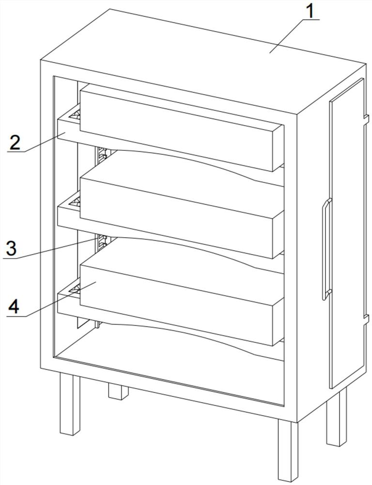
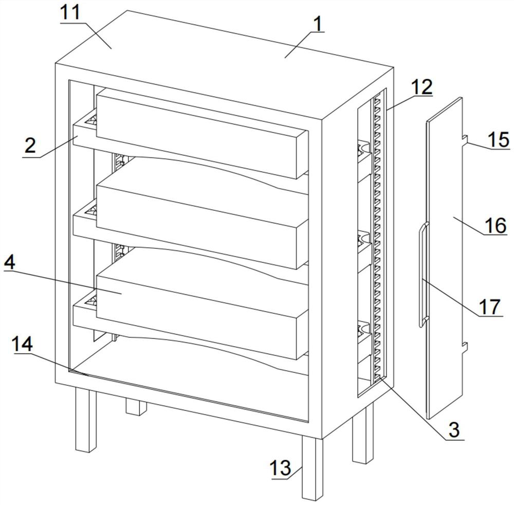
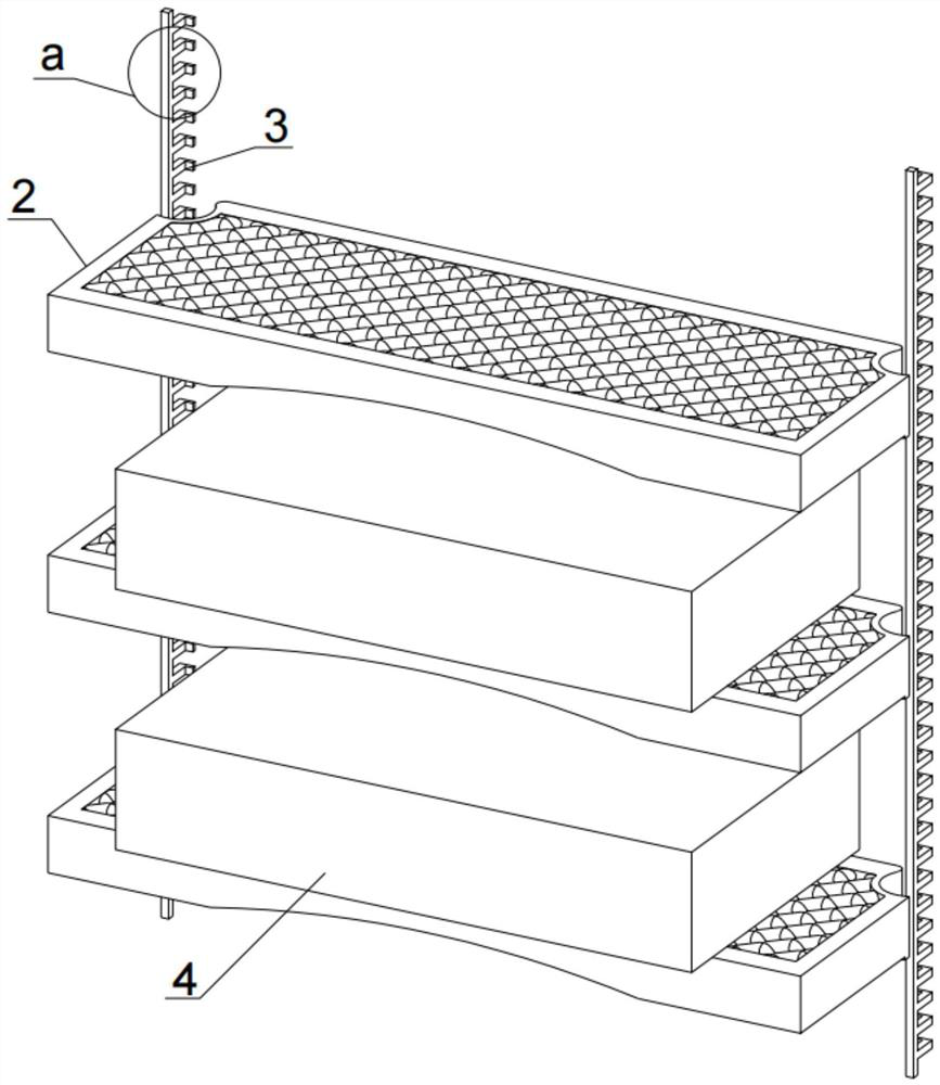
[0026] see Figure 1-5 , the present invention provides a technical solution: a visual monitoring and management device for power transmission lines, including an equipment box 1, an equipment rack 2 is installed inside the equipment box 1, and a management device 4 is installed on the upper surface of the equipment rack 2. The side surface is equipped with a cable rack 3, and the equipment box 1 includes a casing 11. The side surface of the casing 11 is provi...


PUM


Abstract

The invention discloses a visual monitoring management device for power transmission lines. The device comprises an equipment box; an equipment frame is assembled in the equipment box; management equipment is assembled on the upper surface of the equipment frame; and a cabling rack is assembled on the side surface of the equipment frame. The invention provides an equipment box with an equipment rack with a good heat dissipation effect. During use, the management equipment of the visual monitoring equipment for power transmission lines is assembled on the upper surface of the equipment frame, and the heat dissipation effect is ensured by a heat dissipation net on the upper surface of the equipment frame. Then, a handle is pulled open, and a cabinet door is opened. Wires are conveniently connected and arranged on the rear side surface of the management equipment, and the arranged wires can be bound on the outer surface of a binding strip by using a rolling belt. The problems that a server of an existing visual management system for power transmission lines is generally influenced by too many outer ends of monitoring equipment, a single piece of equipment is generally large, and the interlayer structure of a server cabinet is insufficient in strength are effectively solved. Wire arrangement and later-stage wire rearrangement are facilitated, and meanwhile, the heat dissipation effect is good.

Description

technical field [0001] The invention relates to the technical field of visual monitoring and control of power transmission lines, in particular to a visual monitoring and management device for power transmission lines. Background technique [0002] The transmission line is realized by using a transformer to boost the electric energy generated by the generator, and then connecting it to the transmission line through control equipment such as a circuit breaker. In the structural form, the transmission line is divided into an overhead transmission line and a cable line, and the overhead transmission line is erected on the ground. , using insulators and air-insulated power lines, [0003] Overhead lines are composed of wires, overhead ground wires, insulator strings, pole towers, grounding devices, etc. In order to facilitate line management, visual monitoring equipment for monitoring cable conditions is usually installed on the top of the power tower of the circuit, and the mon...

Claims


Application Information

Patent Timeline
IPC IPC(8): H05K7/14H05K7/20
CPCH05K7/14H05K7/1488H05K7/1491H05K7/2039
Inventor 石习双全浩罗朝宇刘康林张存德彭朋温才权卢亦韬韦海朱张华岑宇海甘戈炎杨增强
Owner CHINA SOUTHERN POWER GRID EHV POWER TRANSMISSION COMPANY WUZHOU BUREAU
Learn More