
Inclined platform, substrate conveying device and substrate conveying method

A technology of transmission device and transmission method, which is applied in the direction of transportation and packaging, conveyors, rollers, etc., can solve the problems of excessive etching on the substrate surface, affect the substrate transmission efficiency, and limit the substrate transmission size, so as to improve product quality and maintain product quality. quality effect

Inactive Publication Date: 2021-11-23
MANZ TAIWAN
View PDF7 Cites 0 Cited by
  • Summary
  • Abstract
  • Description
  • Claims
  • Application Information

AI Technical Summary

Problems solved by technology

[0002] A common substrate transfer device usually uses a conveyor line to transfer the substrate to a conveying structure composed of a plurality of conveying rollers, and then moves the substrate to a designated position by a robot arm installed near the conveying structure, or by After the robot arm intercepts the substrate, it lifts the substrate to another group of transmission structures. Although the robot arm can move the substrate horizontally or up and down, the robot arm needs to move step by step, and the size of the moving substrate There are also restrictions, so the size of the substrate is limited, and it takes too much unnecessary time when the robot arm moves, which affects the efficiency of the substrate transfer; in addition, there are still many etching solutions after the wet process Residues on the surface of the substrate, severe cases will cause the problem of over-etching on the surface of the substrate; therefore, how to use innovative design to solve the shortcomings of the harm caused by the residue of the liquid on the substrate surface is still the development of related industries such as substrate transfer devices Issues that the industry and related researchers need to continue to work hard to overcome and solve

Method used


Image

  • Inclined platform, substrate conveying device and substrate conveying method
  • Inclined platform, substrate conveying device and substrate conveying method
  • Inclined platform, substrate conveying device and substrate conveying method

Examples


Embodiment Construction

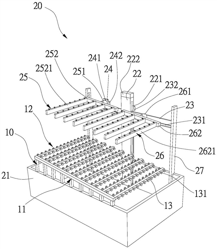
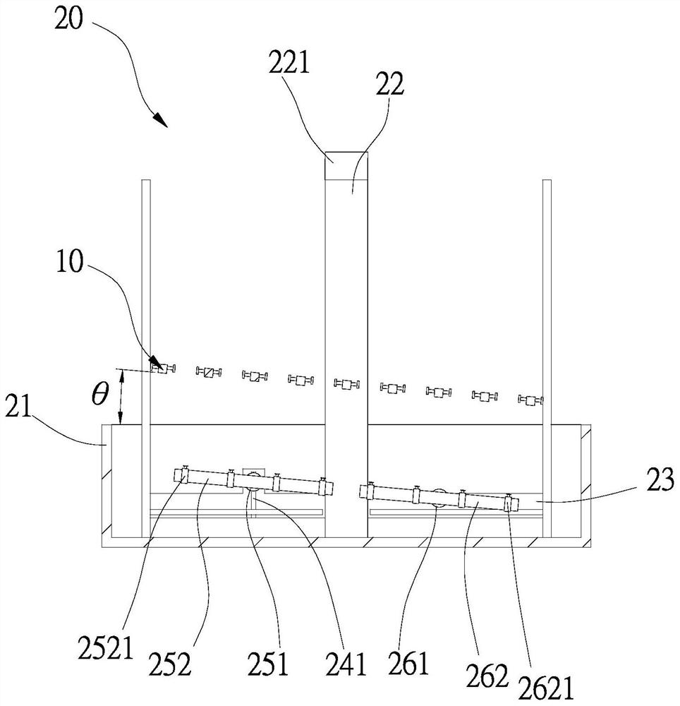
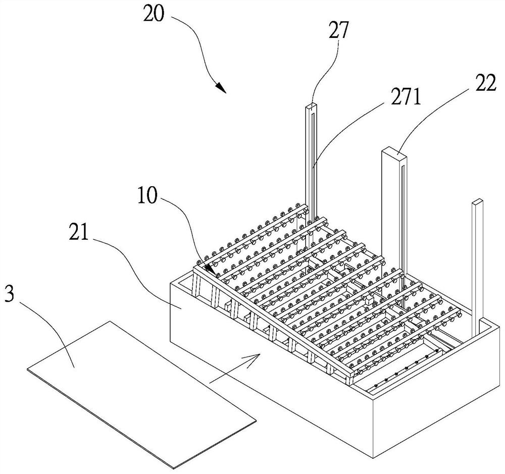
[0094] First, see figure 1 and figure 2 As shown, it is a perspective view of the overall device and a cross-sectional view of the overall device of a preferred embodiment of the substrate transfer device of the present invention, wherein the inclined platform 10 of the present invention is suitable for the substrate transfer device 20, wherein the substrate transfer device 20 includes at least one base Seat 21, which mainly lies in that: the inclined platform 10 is set on the base 21, and an included angle θ is interposed between the inclined platform 10 and the base 21, wherein the included angle θ is between 3 degrees and 10 degrees Between, preferably 5 degrees, that is to say, the inclined platform 10 is erected on the upper surface of the base 21 by a plurality of conveying rollers 13 of unequal height, so that the long side 11 on the left side of the inclined platform 10 Higher than the long side 11 on the right side, and the upper surface of the inclined platform 10 ...


PUM

PropertyMeasurementUnit
angleaaaaaaaaaa

Abstract

The invention discloses an inclined platform and a substrate conveying device prepared by the same. The inclined platform is used for enabling a conveyed substrate or a wet-type process liquid medicine on the surface of the substrate to be dissipated through an inclined angle. The substrate conveying device at least comprises a base and the inclined platform, and is mainly characterized in that the inclined platform is arranged on the base, and an included angle is formed between the inclined platform and the base; therefore, by means of the design that the inclined platform is arranged on the base of the substrate conveying device, liquid medicine left on the surface of the substrate in a wet process can slide down along the inclined angle while the substrate is conveyed, so that the surface of the substrate cannot be damaged due to the residual liquid medicine when the substrate is conveyed, and the advantages of protecting the quality of the conveyed substrate and the like are really achieved.

Description

technical field [0001] The present invention relates to a substrate transfer device and a substrate transfer method thereof, in particular to an inclined platform that enables the liquid of the wet process on the surface of the transferred substrate to dissipate by means of a platform with an inclined angle, and the inclined platform thereby The prepared substrate transfer device and the substrate transfer method thereof. Background technique [0002] A common substrate transfer device usually uses a conveyor line to transfer the substrate to a conveying structure composed of a plurality of conveying rollers, and then moves the substrate to a designated position by a robot arm installed near the conveying structure, or by After the robot arm intercepts the substrate, it lifts the substrate to another group of transmission structures. Although the robot arm can move the substrate horizontally or up and down, the robot arm needs to move step by step, and the size of the moving...

Claims


Application Information

Patent Timeline
Patent Type & Authority Applications(China)
IPC IPC(8): B65G13/00B65G13/12
CPCB65G13/00B65G13/12B65G2201/02
Inventor 黄建凯陈传宜蔡承佑
Owner MANZ TAIWAN
Learn More