Relative phase control circuit and LED constant current system

A technology of control circuit and relative phase, applied in the direction of electrical components, etc., can solve the problem of unable to meet the relative phase, and achieve the effect of improving the input current waveform of the line network

Pending Publication Date: 2021-11-26
SHENZHEN SUNMOON MICROELECTRONICS
View PDF0 Cites 0 Cited by
  • Summary
  • Abstract
  • Description
  • Claims
  • Application Information

AI Technical Summary

Problems solved by technology

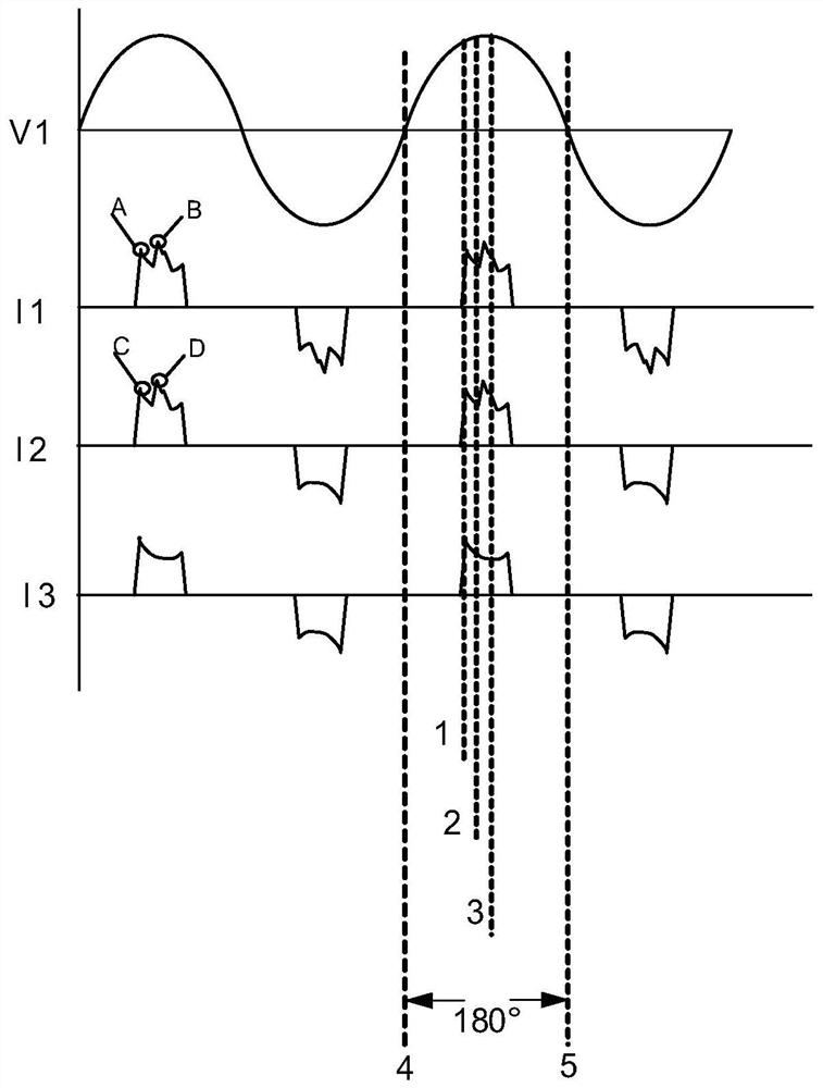
[0004] The main purpose of the present invention is to propose a relative phase control circuit and LED constant current system, aiming to solve the problem that the input current waveform of the line network in the current intelligent LED constant current system cannot meet the relative phase in the IEC 61000-3-23 file, and improve The input current waveform of neutral net in LED constant current system

Method used


Image

  • Relative phase control circuit and LED constant current system
  • Relative phase control circuit and LED constant current system
  • Relative phase control circuit and LED constant current system

Examples


Embodiment Construction

[0044] The following will clearly and completely describe the technical solutions in the embodiments of the present invention with reference to the accompanying drawings in the embodiments of the present invention. Obviously, the described embodiments are only part of the embodiments of the present invention, not all of them. Based on the embodiments of the present invention, all other embodiments obtained by persons of ordinary skill in the art without creative efforts fall within the protection scope of the present invention.

[0045]It should be noted that if there is a directional indication (such as up, down, left, right, front, back...) in the embodiment of the present invention, the directional indication is only used to explain the position in a certain posture (as shown in the accompanying drawing). If the specific posture changes, the directional indication will also change accordingly.

[0046] In addition, if there are descriptions involving "first", "second" and s...


PUM


Abstract

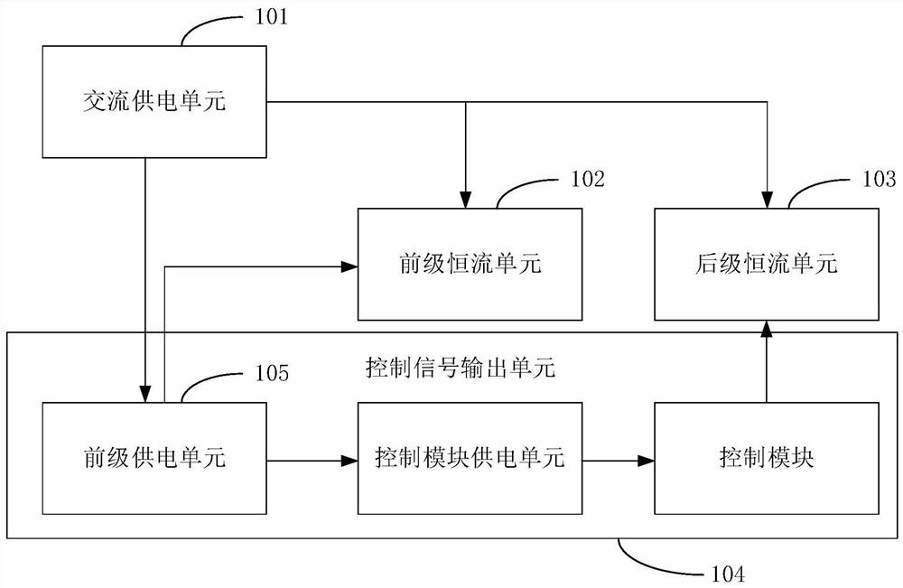
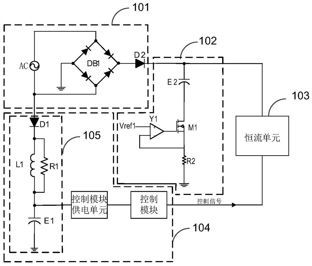
The invention discloses a relative phase control circuit and an LED constant current system. The relative phase control circuit comprises an alternating-current power supply unit, a pre-stage constant-current unit, a post-stage constant-current unit and a control signal output unit; the alternating-current power supply unit is used for outputting alternating-current voltage to the pre-stage constant-current unit and supplying power to the control signal output unit; the pre-stage constant-current unit is used for performing primary constant-current processing on the alternating-current voltage output by the alternating-current power supply unit; the post-stage constant-current unit is used for performing secondary constant-current processing on the current after the constant-current processing of the pre-stage constant-current unit when the control signal output unit outputs the control signal; the control signal output unit comprises a preceding-stage power supply unit, a control module power supply unit and a control module which are sequentially connected in series; and the alternating-current power supply unit is also used for charging the pre-stage power supply unit. According to the invention, the problem that the wire network input current waveform in the LED constant current system cannot meet the relative phase in the IEC 61000-3-23 file is solved, and the wire network input current waveform in the LED constant current system is improved.

Description

technical field [0001] The invention relates to the technical field of LED constant current control, in particular to a relative phase control circuit and an LED constant current system. Background technique [0002] At present, under the background that countries all over the world attach importance to energy saving and emission reduction, LEDs are gradually used in the field of general lighting because of their environmental protection, energy saving, long service life, high brightness, safety, and stability. High-power LED lighting equipment has been widely recognized by the markets of various countries, and is gradually showing a trend of replacing traditional lighting. [0003] The intelligent LED constant current system is the driving power supply of LED lighting equipment, which is a kind of linear power supply. The intelligent LED constant current system mainly includes an AC power supply unit, a pre-stage constant current unit, a control signal output unit and a po...

Claims


Application Information

Patent Timeline
Patent Type & Authority Applications(China)
IPC IPC(8): H05B45/31H05B45/345H05B45/3725
CPCH05B45/31H05B45/345H05B45/3725
Inventor 吴乾炜李照华郭伟峰
Owner SHENZHEN SUNMOON MICROELECTRONICS
Why Eureka
Try Eureka