Cleaning equipment for steel wire rope for petroleum exploitation pumping unit
A technology for oil extraction and cleaning equipment, which is applied in the directions of cleaning methods, cleaning methods and utensils, chemical instruments and methods using tools, etc., and can solve the problems of limited cleaning effect of ropes and inability to penetrate deep into ropes.
- Summary
- Abstract
- Description
- Claims
- Application Information
AI Technical Summary
Problems solved by technology
Method used
Image


Examples
Embodiment 1
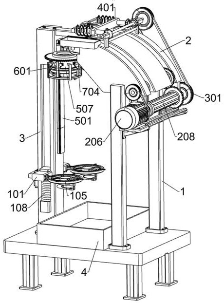
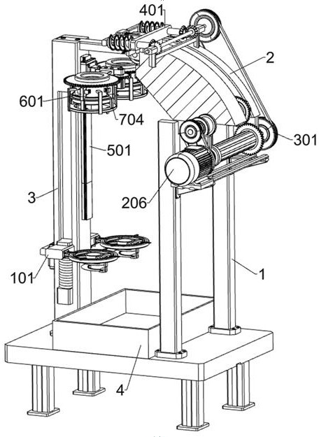
[0038] A kind of wire rope cleaning equipment used for oil extraction pumping unit, such as Figure 1-Figure 3 As shown, it includes end cleaning unit, traction unit, power transmission unit, deep cleaning unit, rotation unit, auxiliary cleaning unit, main support 1, fixed block 2, fixed rod 3, collection box 4, first roller 5 and second Two rollers 6; the top of main support 1 is welded with fixed block 2; the front bolt of main support 1 is connected with fixed rod 3; the front side wall bolt of fixed block 2 is connected with the upper end of fixed rod 3; the upper surface of main support 1 is placed There is a collection box 4; the right part of the front side wall of the fixed block 2 is rotatably connected with a first roller 5; the left part of the front side wall of the fixed block 2 is rotatably connected with a second roller 6; the lower part of the fixed rod 3 is connected with an end cleaning unit The rear part of the fixed block 2 is connected with a traction unit...
Embodiment 2
[0056] On the basis of Example 1, such as Figure 1-Figure 3 ,as well as Figure 15-Figure 17 As shown, an oil dirt collection unit is also included, and the bottom of the third fixed mount 503 is provided with an oil dirt collection unit. Push plate 705, wedge-shaped block 706; The bottom of the third fixed frame 503 is fixedly connected with the fourth fixed frame 701; The left and right sides of the fourth fixed frame 701 are respectively fixed with an annular collecting plate 702, and are located in the adjacent group respectively. The bottom of the third annular support 507; the left and right sides of the bottom of the two annular collecting plates 702 are each affixed with an elastic piece 703; each group of left and right adjacent two elastic pieces 703 are respectively affixed with a fourth An annular support 704 ; an annular push plate 705 is affixed to the upper parts of the two fourth annular supports 704 ; a wedge block 706 is affixed to the lower part of each se...
Embodiment 3
[0060] On the basis of Example 2, such as Figure 1-Figure 3 ,as well as Figure 10-Figure 14 As shown, it also includes a grease scraping unit, the upper part of the fixed block 2 is provided with a grease scraping unit, and the grease scraping unit includes a fifth fixed frame 801, a third electric slider 802, a third motor 803, and a fifth rotating shaft 804, collection inclined plate 805, elastic scraper 806 and collection box 807; the left and right parts of the top of the fixed block 2 are respectively fixedly connected with a fifth fixed frame 801; the insides of the two fifth fixed frames 801 are respectively slidably connected with a first Three electric sliders 802; each bolt at the rear of the two third electric sliders 802 is connected with a third motor 803; the upper surfaces of the two third electric sliders 802 are respectively rotatably connected with a fifth rotating shaft 804; The output shaft of the third motor 803 is respectively affixed to the fifth rota...
PUM
 Abstract
Description
Claims
Application Information
 - R&D
- Intellectual Property
- Life Sciences
- Materials
- Tech Scout
- Unparalleled Data Quality
- Higher Quality Content
- 60% Fewer Hallucinations
Browse by: Latest US Patents, China's latest patents, Technical Efficacy Thesaurus, Application Domain, Technology Topic, Popular Technical Reports.
© 2025 PatSnap. All rights reserved.Legal|Privacy policy|Modern Slavery Act Transparency Statement|Sitemap|About US| Contact US: help@patsnap.com