Transport case special for laboratory
A transport box and laboratory technology, applied in the field of laboratory equipment, can solve the problems of poor anti-collision and anti-falling ability of the transport box, single structure of the transport box, etc., to increase the anti-collision and anti-fall protection ability, easy to carry, and reduce damage. The effect of the probability of
- Summary
- Abstract
- Description
- Claims
- Application Information
AI Technical Summary
Problems solved by technology
Method used
Image

Examples
Embodiment Construction
[0029] The present invention will be described in further detail below in conjunction with the accompanying drawings and embodiments, so that those skilled in the art can implement it with reference to the description.
[0030] It should be understood that terms such as "having", "comprising" and "including" used herein do not exclude the presence or addition of one or more other elements or combinations thereof.
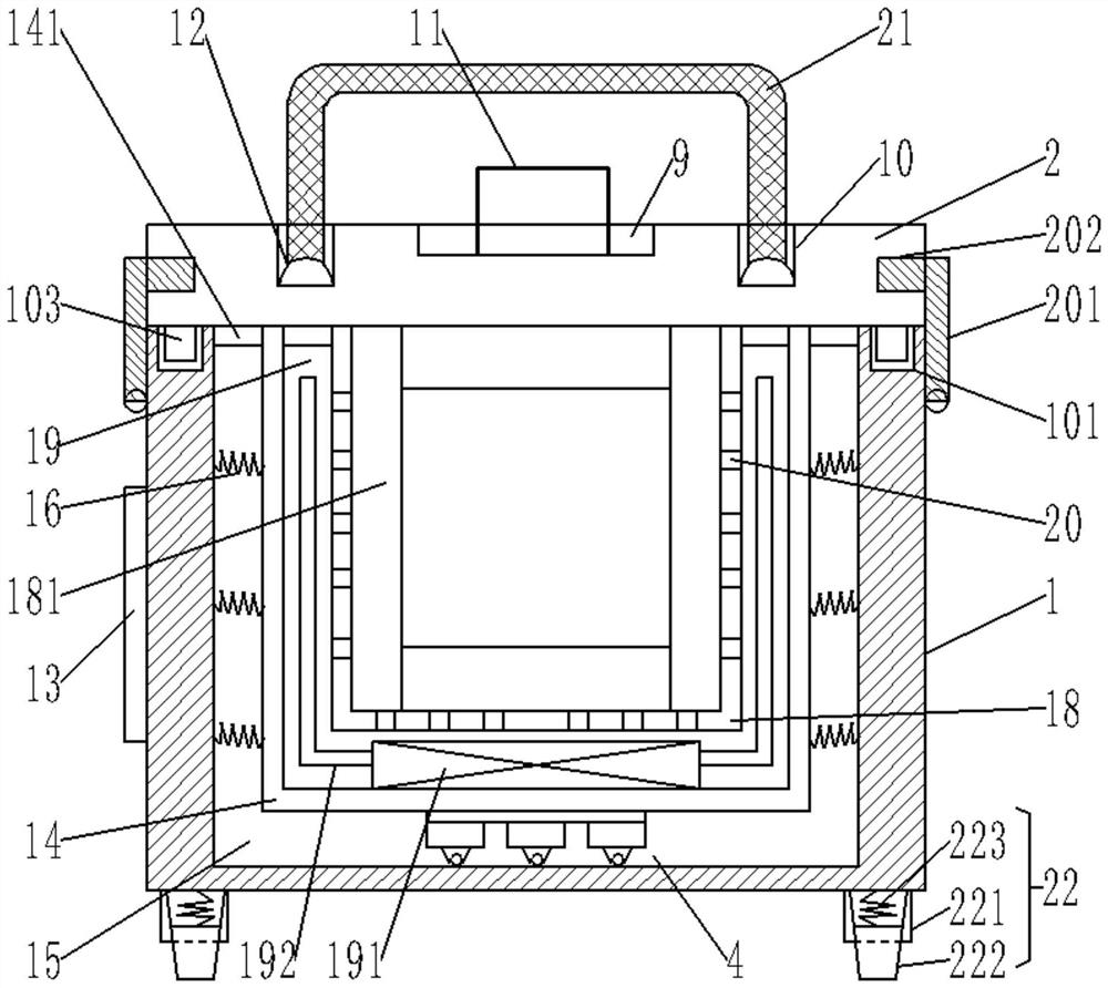
[0031] Such as Figure 1-Figure 4 As shown, the present invention provides a special transport case for laboratories, comprising: a case body 1, a case cover 2 is provided on its upper end, and an anti-collision strip 23 is provided on the vertical corner of the case body 1, the case body 1 is provided with a first liner 14, and between the first liner 14 and the box 1 is an anti-fall layer 15, and the anti-fall layer 15 is provided with a mobile energy-absorbing member 4 and a plurality of transverse springs 16. The moving energy-absorbing member 4 is arranged at ...
PUM
 Abstract
Description
Claims
Application Information
PatSnap Eureka turns technology decisions into work you can execute. Powered by our Innovation Knowledge Graph, it runs expert workflows across engineering, life sciences, materials and intellectual property. Get your review-ready output in minutes.


