Method and device for detecting on/off of bypass relay in boost chopper circuit

A technology of step-up chopping and switch state, which is applied in the field of power electronics, can solve the problems of increased inductor current and damage to power devices, and achieve the effect of reducing the probability of being damaged

Active Publication Date: 2015-08-05
SUNGROW POWER SUPPLY CO LTD
View PDF7 Cites 12 Cited by
  • Summary
  • Abstract
  • Description
  • Claims
  • Application Information

AI Technical Summary

Problems solved by technology

[0004] If the boost chopper circuit starts to work, but the bypass relay is still closed,

Method used


Image

  • Method and device for detecting on/off of bypass relay in boost chopper circuit
  • Method and device for detecting on/off of bypass relay in boost chopper circuit
  • Method and device for detecting on/off of bypass relay in boost chopper circuit

Examples


Example Embodiment

[0042] The technical solutions in the embodiments of the present invention will be clearly and completely described below with reference to the accompanying drawings in the embodiments of the present invention. Obviously, the described embodiments are only a part of the embodiments of the present invention, but not all of the embodiments. Based on the embodiments of the present invention, all other embodiments obtained by those of ordinary skill in the art without creative efforts shall fall within the protection scope of the present invention.
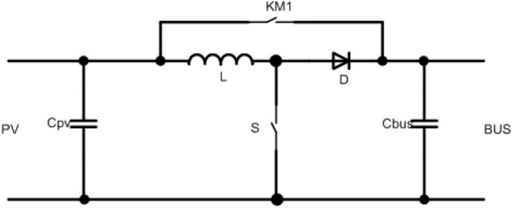
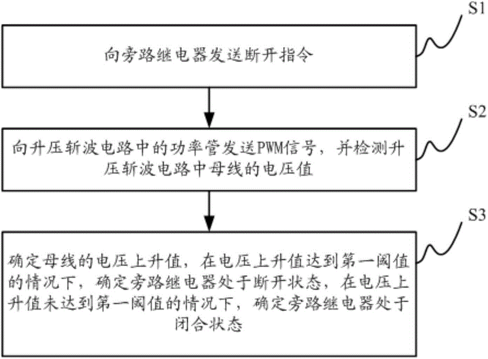
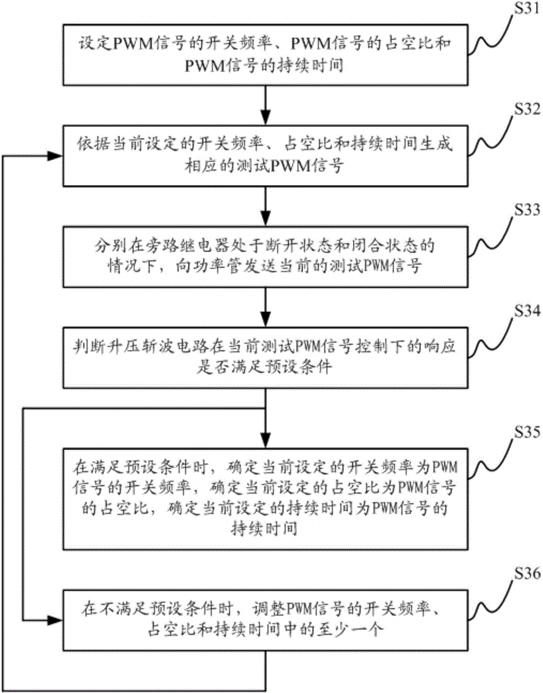
[0043] The invention discloses a switching state detection method of a bypass relay in a boost chopper circuit. Based on the method, the switching state of the bypass relay can be accurately detected, thereby reducing the probability of damage to a power device in the boost chopper circuit.

[0044] see figure 2 , figure 2 It is a flowchart of a method for detecting the switching state of a bypass relay in a boost chopper circuit d...


PUM


Abstract

The invention discloses a method for detecting the on/off of a bypass relay in a boost chopper circuit, and the method comprises the steps: transmitting a switching-off instruction to the bypass relay, wherein the switching-off instruction is used for controlling the bypass relay to carry out switching-off operation; transmitting a PWM signal to a power tube in the boost chopper circuit, and detecting a voltage value of a bus in the boost chopper circuit, wherein the PWM signal can guarantee that a current passing through the power tube is within a safety range; determining the voltage increase value of the bus: determining that the bypass relay is switched off if the voltage increase value reaches a first threshold value; determining that the bypass relay is switched on if the voltage increase value does not reach a first threshold value. The method provided by the invention can accurately determine the on/off states of the bypass relay, and can reduce the damage possibility of a power device in the boost chopper circuit. The invention also discloses a device for detecting the on/off of the bypass relay in the boost chopper circuit.

Description

technical field [0001] The invention belongs to the technical field of power electronics, and in particular relates to a method and a device for detecting a switch state of a bypass relay in a step-up chopper circuit. Background technique [0002] Boost chopper circuit (boost circuit) is a relatively common DC boost circuit. [0003] In order to reduce the forward channel impedance of the boost chopper circuit and improve the conversion efficiency of the boost chopper circuit, a bypass relay is often set in the boost chopper circuit. When the input voltage is low, the boost chopper circuit work, the control bypass relay is disconnected, when the input voltage is high, the step-up chopper circuit does not need to work, and the control bypass relay is closed. figure 1 shows a boost chopper circuit with a bypass relay including input capacitor C PV , Bus capacitance C bus , a power tube S, an inductor L, a diode D and a bypass relay KM1, wherein the bypass relay KM1 is conne...

Claims


Application Information

Patent Timeline
IPC IPC(8): G01R31/327
Inventor 张凤岗袁利华苏振东张志飞
Owner SUNGROW POWER SUPPLY CO LTD
Why Eureka
Try Eureka