
Integral tension-compression pad curved surface line drawing plate, design method and using method

A design method and technology of tension and pressure pads, applied in the direction of applying stable tension/pressure to test the strength of materials, measuring devices, instruments, etc., can solve the problem of difficult positioning of lines on the surface of structures with large curvature, poor accuracy of line drawing methods, and relative Large position error and other problems, to achieve the effect of improving test loading accuracy and test safety and reliability, improving sticking strength, and improving position accuracy

Pending Publication Date: 2021-11-30
CHINA AIRPLANT STRENGTH RES INST
View PDF0 Cites 0 Cited by
  • Summary
  • Abstract
  • Description
  • Claims
  • Application Information

AI Technical Summary

Problems solved by technology

[0005] The purpose of this application is to provide an integral tension and pressure pad curved line drawing board, design method and use method to solve the poor accuracy of the line drawing method existing in the prior art, and the relative position error between the tension and pressure pads at the same loading point is large , it is difficult to draw lines for positioning on the surface of large curvature structures, and at least one of the problems of low efficiency of on-site line drawing

Method used


Image

  • Integral tension-compression pad curved surface line drawing plate, design method and using method
  • Integral tension-compression pad curved surface line drawing plate, design method and using method
  • Integral tension-compression pad curved surface line drawing plate, design method and using method

Examples


Embodiment Construction

[0036] In order to make the purpose, technical solution and advantages of the application more clear, the technical solution in the embodiment of the application will be described in more detail below in conjunction with the drawings in the embodiment of the application. In the drawings, the same or similar reference numerals denote the same or similar elements or elements having the same or similar functions throughout. The described embodiments are some, but not all, embodiments of the application. The embodiments described below by referring to the figures are exemplary, and are intended to explain the present application, and should not be construed as limiting the present application. Based on the embodiments in this application, all other embodiments obtained by persons of ordinary skill in the art without creative efforts fall within the protection scope of this application. Embodiments of the present application will be described in detail below in conjunction with th...


PUM

PropertyMeasurementUnit
thicknessaaaaaaaaaa

Abstract

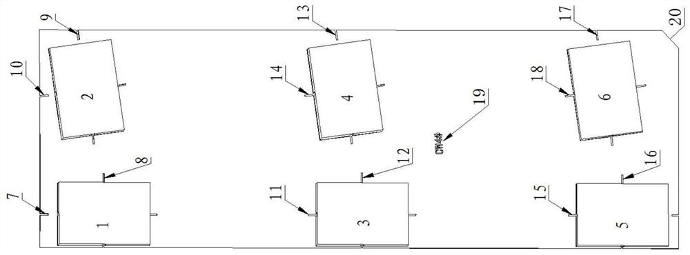
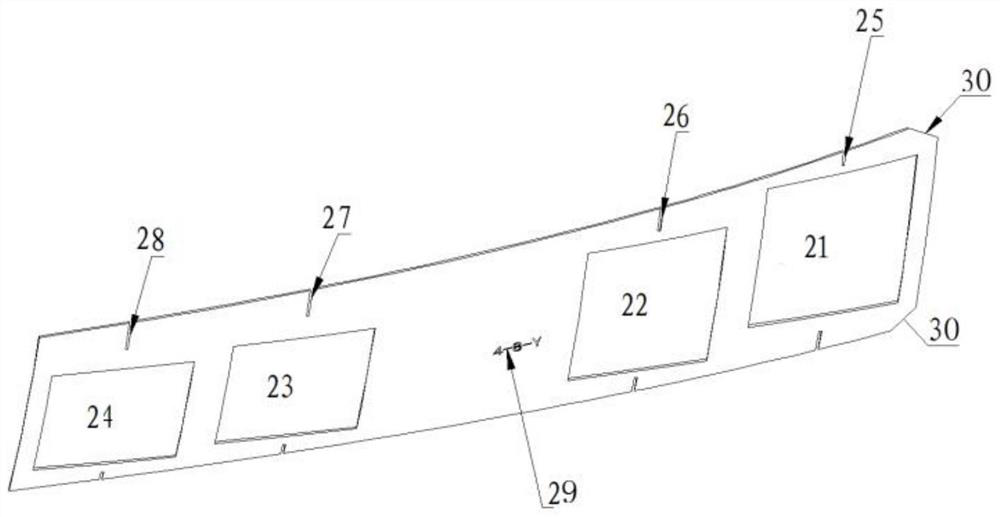
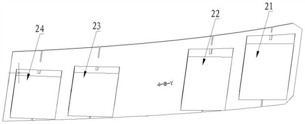
The invention belongs to the field of auxiliary positioning tools for test loading, and particularly relates to an integral tension-compression pad curved surface line drawing plate, a design method and a using method. The design method comprises the steps that firstly, equal-thickness stretching is conducted on an aircraft surface skin in a loading point area to obtain a line drawing plate main body, and the line drawing plate main body is shaped according to the boundary of a tension-compression pad; secondly, a first groove is formed in the line drawing plate main body according to the shape of the tension-compression pad; thirdly, a second groove used for positioning is formed in the line drawing plate main body; fourthly, a third groove is formed in the outer surface of the line drawing plate main body and used for marking the number of the line drawing plate; fifthly, a fourth groove is formed in one end of the line drawing plate main body and used for marking the pasting direction of the line drawing plate; sixthly, after the line drawing plate is designed according to the first step to the fifth step, the line drawing plate is machined.

Description

technical field [0001] The application belongs to the field of auxiliary positioning tooling for test loading, and in particular relates to an integral tension and pressure pad curved line drawing board, a design method and a use method. Background technique [0002] The tension and pressure pad lever system is one of the main loading methods in static / fatigue tests of aircraft structures. In the test preparation stage, it is necessary to paste tension and compression pads on the surface of the aircraft for test loading. Before pasting the tension and pressure pads on the surface of the aircraft, it is necessary to draw a frame line with the same width as the tension and pressure pads on the surface of the test piece according to the benchmarks such as beams, ribs and frame positions, as the basis for pasting and positioning the tension and pressure pads. Therefore, the line drawn on the tension and pressure pad directly affects the accuracy of the sticking position of the ...

Claims


Application Information

Patent Timeline
Patent Type & Authority Applications(China)
IPC IPC(8): G01N3/08G01N3/02
CPCG01N3/08G01N3/02G01N2203/0017G01N2203/0605
Inventor 王彬郑建军王高利王孟孟刘玮朱亚辉
Owner CHINA AIRPLANT STRENGTH RES INST
Learn More