
Plastic particle screening device

A screening device and technology for plastic granules, applied in the field of plastic processing, can solve the problems of short adhesion time, influence on the quality of plastic products, incomplete screening, etc., and achieve the effect of thorough screening

Pending Publication Date: 2021-12-03
霍山诚宇新材料科技有限公司
View PDF0 Cites 1 Cited by
  • Summary
  • Abstract
  • Description
  • Claims
  • Application Information

AI Technical Summary

Problems solved by technology

[0002] The traditional production equipment inputs the plastic granules produced by the plastic granulator to the extruder through the plastic granule feeder, and the plastic granules produced by the plastic granulator may have problems of different sizes, resulting in the quality of plastic products. Therefore, when using plastic granules to make finished products, it is necessary to sieve plastic granules, and use plastic granules of different sizes and grades to make different finished products. The sieve plate in the traditional sieving machine is a flat plate, that is, multiple A flat sieve plate sieves the plastic particles. When the particles reach the upper sieve plate, they will quickly fall to the lower sieve plate, and then fall down to the lower sieve plate, so the plastic particles go down from the upper sieve plate. When the sieve falls, the attachment time on the sieve plates at all levels at the lower end is short, which easily leads to incomplete sieving

Method used


Image

  • Plastic particle screening device
  • Plastic particle screening device
  • Plastic particle screening device

Examples


Embodiment

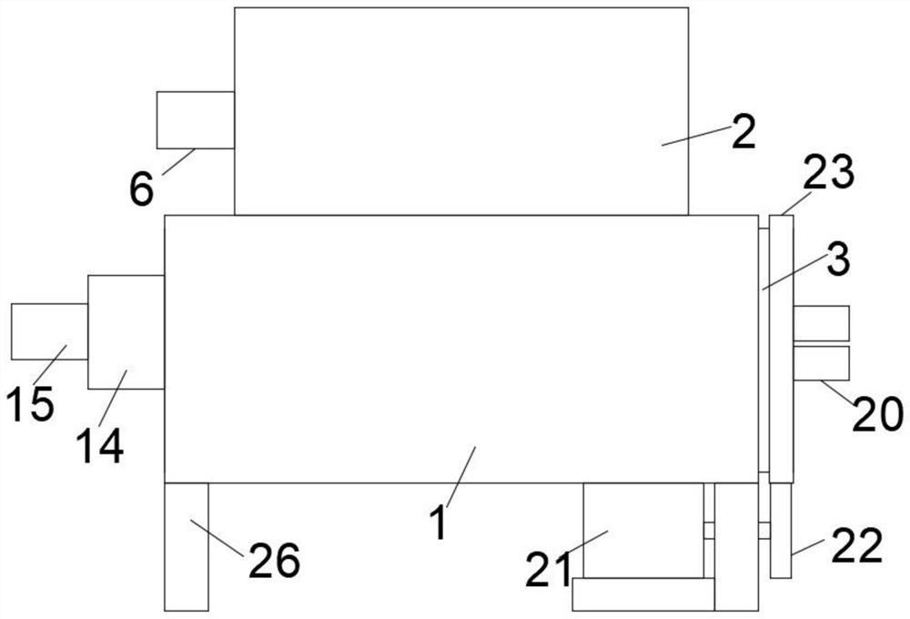
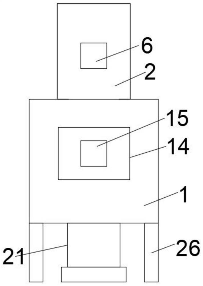
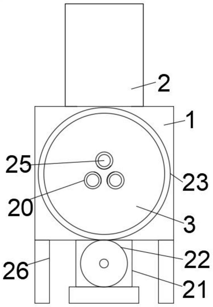
[0026] Embodiment: Pour the plastic granules into the feeding box 2, and pour the first batch of plastic granules in the feeding box 2 into the first screen part 11 through the feeding baffle plate 9 through the segmental feeding device, and pass through the second batch of plastic granules in the feeding box 2 A sieve part 11 filters small plastic particles, and at this time, the small plastic particles sieved into the first sieve part 11 are conveyed to the discharge pipe 20 corresponding to the first sieve part 11 through the conveying device for discharge Collecting, the cylinder 3 is driven to rotate through the transmission device, the first screen part 11 is rotated out directly below the blanking baffle 9, so that the second screen part 12 is located directly below the blanking baffle 9, and the plastic particles at this time enter The upper end of the second screen part 12, through the second screen part 12, the plastic particles are screened again, and the large plast...


PUM


Abstract

The invention discloses a plastic particle screening device. The plastic particle screening device comprises a box body supported by supporting columns, a feeding box is arranged at the upper end of the box body, a segmented discharging device is arranged in the feeding box, a discharging baffle is arranged at the position, located at the lower end of the segmented discharging device, of the feeding box, a cylinder movably connected to the box body is arranged below the discharging baffle, the cylinder abuts against the lower end face of the discharging baffle, the interior of the cylinder is divided into a first screen part, a second screen part and a material leakage net part through partition plates at equal angles, a first transmission device is arranged at the lower end of the box body, a material conveying device opposite to the first screen part, the second screen part and the material leakage net part is arranged in the cylinder, and one end of the cylinder is provided with a discharge pipe opposite to the first screen part, the second screen part and the leakage net part. According to the plastic particle screening device, the cylinder is driven to rotate through the transmission device, so that the staying time of plastic particles on the first screen part, the second screen part and the material leaking net part is the same, the plastic particles can be uniformly screened, and then screening is more thorough.

Description

technical field [0001] The invention relates to the technical field of plastic processing, in particular to a plastic particle screening device. Background technique [0002] The traditional production equipment inputs the plastic granules produced by the plastic granulator to the extruder through the plastic granule feeder, and the plastic granules produced by the plastic granulator may have problems of different sizes, resulting in the quality of plastic products. Therefore, when using plastic granules to make finished products, it is necessary to sieve plastic granules, and use plastic granules of different sizes and grades to make different finished products. The sieve plate in the traditional sieving machine is a flat plate, that is, multiple A flat sieve plate sieves the plastic particles. When the particles reach the upper sieve plate, they will quickly fall to the lower sieve plate, and then fall down to the lower sieve plate, so the plastic particles go down from th...

Claims


Application Information

Patent Timeline
IPC IPC(8): B29B13/10B07B1/22B07B1/46B07B1/42
CPCB29B13/10B07B1/22B07B1/42B07B1/4645
Inventor 赵厚旺袁学刚杜林
Owner 霍山诚宇新材料科技有限公司
Learn More