
Balance shaft support and balance suspension device

A technology of balance shaft support and balance suspension, which is applied in the direction of suspension, cantilever mounted on pivot, transportation and packaging, etc., which can solve problems such as poor ride comfort, poor tire adhesion, and wheel slippage

Pending Publication Date: 2021-12-03
东风汽车底盘系统有限公司
View PDF9 Cites 0 Cited by
  • Summary
  • Abstract
  • Description
  • Claims
  • Application Information

AI Technical Summary

Problems solved by technology

However, there are also obvious deficiencies in the leaf spring balanced suspension. Because of the high rigidity of the leaf spring, the ride comfort is poor when it is unloaded, and because the load acting on the middle and rear axles is small, the poor adhesion of the tires will easily lead to insufficient driving force and wheel slippage. and wear; since the axle loads of the middle and rear axles are transmitted to the balance shaft bracket through the leaf spring, the stress situation is complicated. Therefore, the part below the balance shaft hole of the bracket is only connected with the lower thrust rod at present, and only bears the longitudinal force. Bearing vertical load, its structure and strength design are relatively less demanding

Method used


Image

  • Balance shaft support and balance suspension device
  • Balance shaft support and balance suspension device
  • Balance shaft support and balance suspension device

Examples


Embodiment Construction

[0023] The principles and features of the present invention are described below in conjunction with the accompanying drawings, and the examples given are only used to explain the present invention, and are not intended to limit the scope of the present invention.

[0024] This embodiment provides a balance shaft bracket. By designing the structure of the balance shaft bracket, the traditional connection method is changed, so as to achieve the purpose of changing the force effect and improving the comfort of the vehicle.

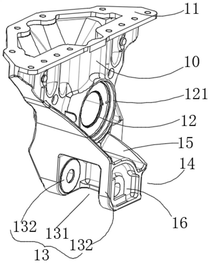
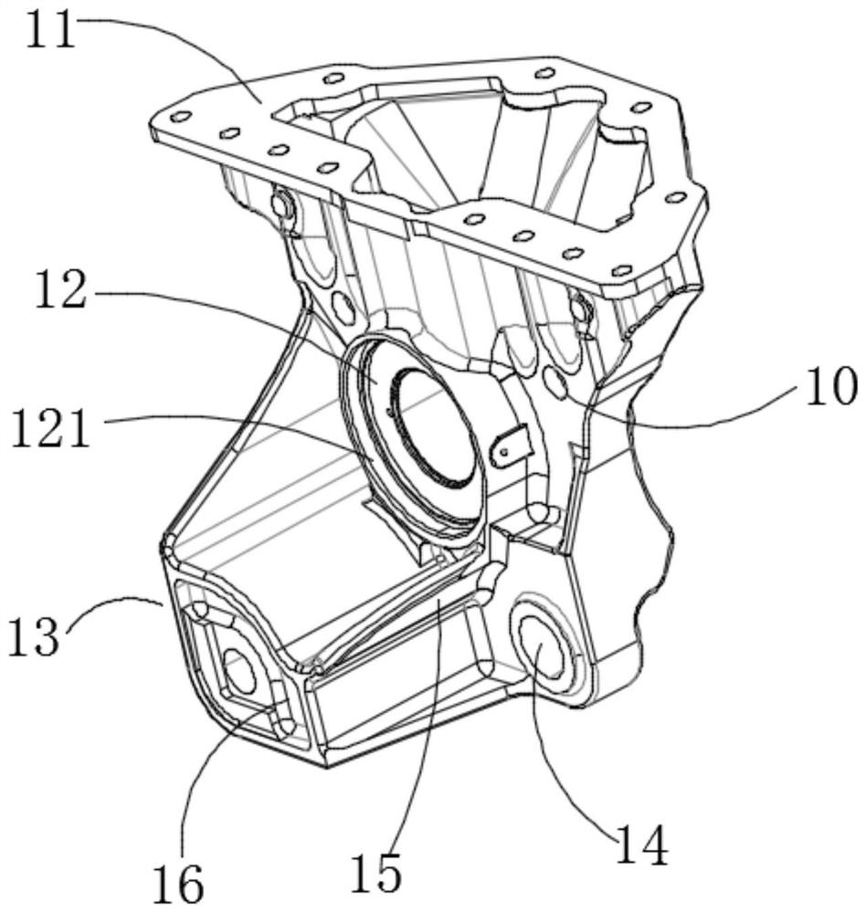
[0025] Specifically, see Figure 2-Figure 6 , the provided balance shaft bracket includes a body 10, which is manufactured by casting and then processed into a one-piece structure.

[0026] The upper part of the body 10 is provided with a vehicle frame installation position 11, where the vehicle frame installation position 11 is mainly used to facilitate the fixed installation of the vehicle frame. In the balance suspension device, the structure of the vehicl...


PUM


Abstract

The invention discloses a balance shaft support and a balance suspension device, the balance suspension device comprises frames arranged at intervals in mirror symmetry, each frame is fixedly provided with a balance shaft support, and the frames are fixed with frame mounting positions on the balance shaft supports; each balance shaft support comprises a body, a frame installation position is arranged on the upper portion of the body, a through bearing hub installation position of a hole-shaped structure is arranged in the middle of the body in the vertical direction, and a guide arm mounting position and a thrust rod mounting position are further arranged on the body. The guide arm mounting position and the thrust rod mounting position are respectively arranged on the left side and the right side of the lower part of the body; according to the balance shaft support for the suspension, the structure of the upper half portion of an original balance shaft support is reserved, and only the structure of the portion below the balance shaft hole is designed in an improved mode; the traditional stress mode is changed, and the comfort performance of a no-load vehicle is greatly improved, and the tire adhesiveness is greatly improved.

Description

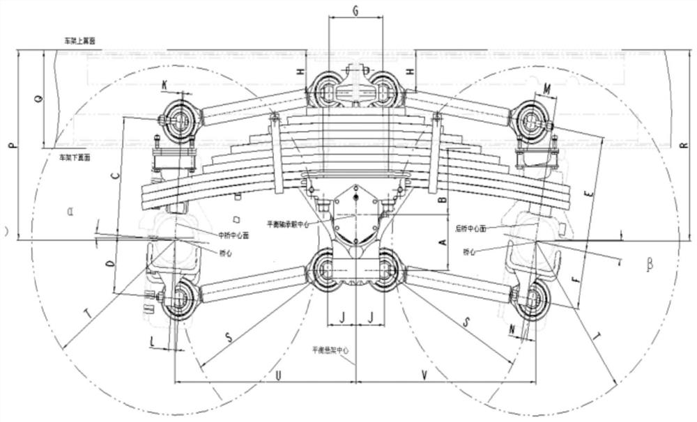
technical field [0001] The invention relates to the technical field of balance suspension, in particular to a balance shaft bracket and a balance suspension device equipped with the balance shaft bracket. Background technique [0002] At present, most of the rear axles of existing 6X4 heavy-duty trucks adopt leaf spring balanced suspension (the specific structure is as follows: figure 1 As shown), the middle and rear axles are separated at both ends of the leaf spring, the middle part of the axle is connected to the frame through the upper thrust rod, the lower end is connected to the balance shaft bracket through the lower thrust rod, and the middle part of the leaf spring is realized through the bearing hub and the balance shaft support. Hinged so that raising one axle will lower the other, and since the leaf springs are of equal length at both ends, the vertical loads on the middle and rear axles are equal in any case. [0003] Compared with other suspension forms, the l...

Claims


Application Information

Patent Timeline
IPC IPC(8): B60G7/02
CPCB60G7/02B60G2204/148
Inventor 李俊石朝阳樊愉孙艳新贺佳鑫柴培洋
Owner 东风汽车底盘系统有限公司
Learn More