Liquid fuel furnace

A liquid fuel and fuel technology, applied in the burner, combustion method, combustion type and other directions, can solve the problems of high cost, weak firepower, complex overall structure, etc., and achieve the effect of low cost and simple structure

Pending Publication Date: 2021-12-03
胡夏尔
View PDF1 Cites 4 Cited by
  • Summary
  • Abstract
  • Description
  • Claims
  • Application Information

AI Technical Summary

Problems solved by technology

[0004] Electric heating gasification devices generally use mains power supply, so additional power supply components and electric controls need to be configured. During cold start, the firepower is always in a weak state

Method used


Image

  • Liquid fuel furnace
  • Liquid fuel furnace
  • Liquid fuel furnace

Examples


no. 1 example

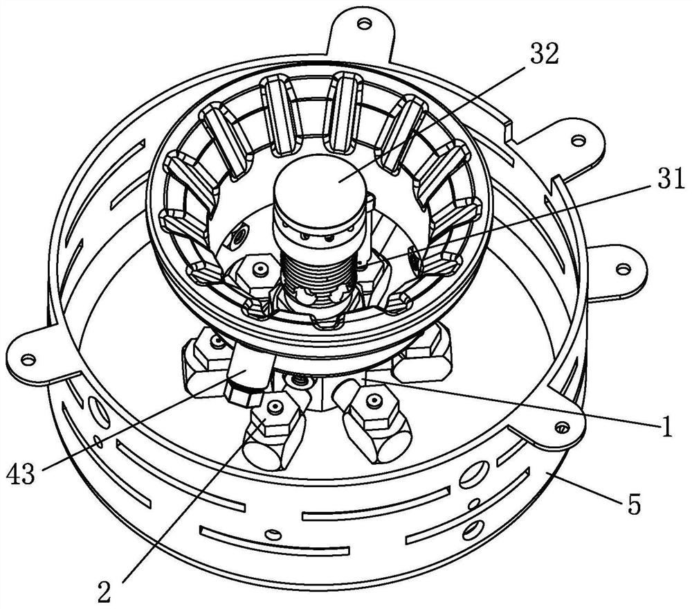
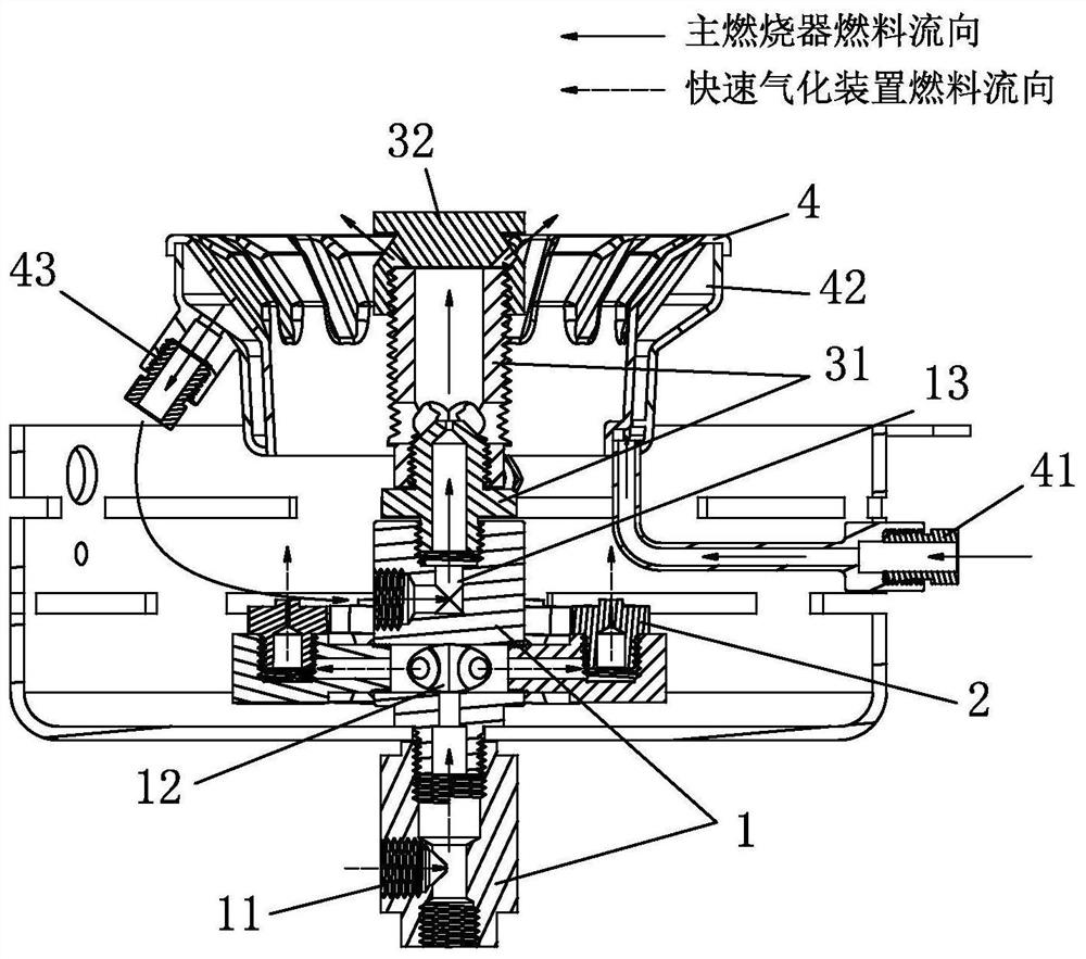
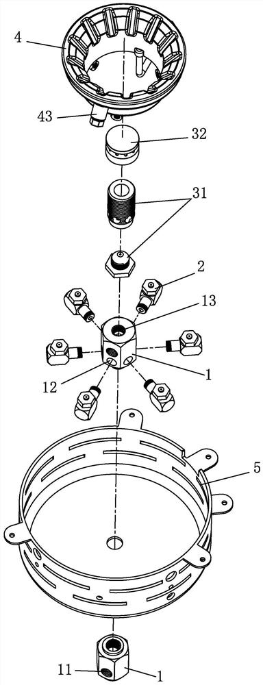
[0027] see Figure 1-Figure 6 , the liquid fuel furnace, the main burner, gasification ring 4 and rapid gasification device, the rapid gasification device includes through the main body 1, several atomization combustion nozzles 2, specifically, the present embodiment preferably six atomization Combustion nozzle 2, the main body 1 is located below the main burner, the main body 1 is provided with a main body fuel inlet 11 and a main body fuel distribution channel 12, and the main body fuel inlet 11, the main body fuel distribution channel 12, and the atomizing combustion nozzle 2 are sequentially connected The atomization combustion nozzle 2 is radially distributed on the periphery of the main body 1, the atomization combustion nozzle 2 is provided with a nozzle opening, and the nozzle opening is from bottom to top towards the gasification ring 4, and the nozzle opening gradually changes from its ejection direction Small, so that the sprayed liquid fuel can be atomized naturall...


PUM


Abstract

The invention discloses a liquid fuel furnace which comprises a main combustor, a gasification ring and a rapid gasification device, wherein the rapid gasification device comprises a main body and a plurality of atomization combustion nozzles, the main body is located below the main combustor, the main body is provided with a main body fuel inlet and a main body fuel shunting channel, the main body fuel inlet, the main body fuel shunting channel and the atomization combustion nozzles are communicated in sequence, the atomization combustion nozzles are distributed on the periphery of the main body in a radial mode and provided with nozzle openings, and the nozzle openings face the gasification ring from bottom to top. When the liquid fuel furnace is in cold start, the rapid gasification device sprays atomized liquid fuel through the atomization combustion nozzles and combusts the atomized liquid fuel, so that firepower is larger during cold start, the gasification ring can be heated more rapidly during combustion, the temperature of the gasification ring can be increased more rapidly, and the liquid fuel furnace enters a high-fire use state more rapidly.

Description

technical field [0001] The present invention relates to a liquid fuel stove. Background technique [0002] Chinese Patent Document No. CN107543214A discloses a new type of liquid fuel stove, including a gasification ring and a direct injector. The gasification ring is respectively connected with a fuel inlet pipeline and a fuel output pipeline, and the fuel output pipeline is connected to the input end of the direct injector. The fuel inlet pipeline is provided with a safety valve for shutting off or conducting the intake pipeline, and the fuel output pipeline is sequentially provided with an electrothermal gasification device for vaporizing liquid fuel and for adjusting fuel flow, A control valve that controls ignition and flameout. [0003] This liquid fuel stove is equipped with an electric heating gasification device, and the electric heating gasification device is used as an auxiliary gasification device during cold start to make the liquid fuel gasify faster, which ca...

Claims


Application Information

Patent Timeline
Patent Type & Authority Applications(China)
IPC IPC(8): F23D11/22F23D11/38F23D11/44F23D11/36
CPCF23D11/22F23D11/38F23D11/443F23D11/36
Inventor 胡夏尔
Owner 胡夏尔
Why Eureka
Try Eureka