
Server internal cooling device facilitating element installation

A technology for cooling devices and installing components, which is applied in the direction of instruments, digital data processing parts, electrical digital data processing, etc. High, affecting the service life of the computer, reducing the working efficiency of the server, etc., to achieve the effect of low cost, easy wiring, and convenient ventilation

Active Publication Date: 2021-12-03
SUZHOU LANGCHAO INTELLIGENT TECH CO LTD
View PDF4 Cites 0 Cited by
  • Summary
  • Abstract
  • Description
  • Claims
  • Application Information

AI Technical Summary

Problems solved by technology

[0002] The composition of the server includes processors, hard disks, memory, system buses, etc., which are similar to general-purpose computer architectures, but due to the need to provide highly reliable services, processing power, stability, reliability, security, scalability, scalability The requirements for management and other aspects are relatively high, and the dust prevention and heat dissipation of the server is also the most common problem. In daily work, the computer server will generate heat when it works for a long time. Failure to dissipate heat in time will reduce the working efficiency of the server.
Existing servers usually dissipate heat through the cooling device carried by the server itself. In this way, the heat dissipation performance of the server is poor, and some of them use air-cooled direct blowing to dissipate heat. However, this can only have a partial cooling effect on the server and cannot Make the server fully dissipate heat, which will seriously affect the service life of the computer

Method used


Image

  • Server internal cooling device facilitating element installation
  • Server internal cooling device facilitating element installation
  • Server internal cooling device facilitating element installation

Examples


Embodiment Construction

[0032] The present invention will be further described below in conjunction with the accompanying drawings and embodiments.

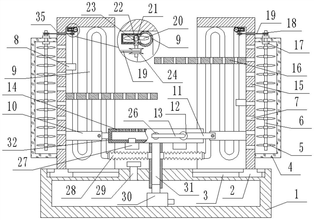
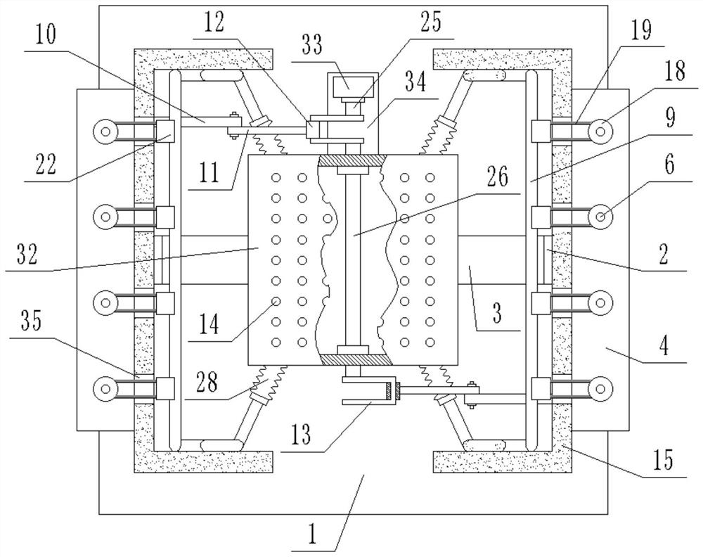
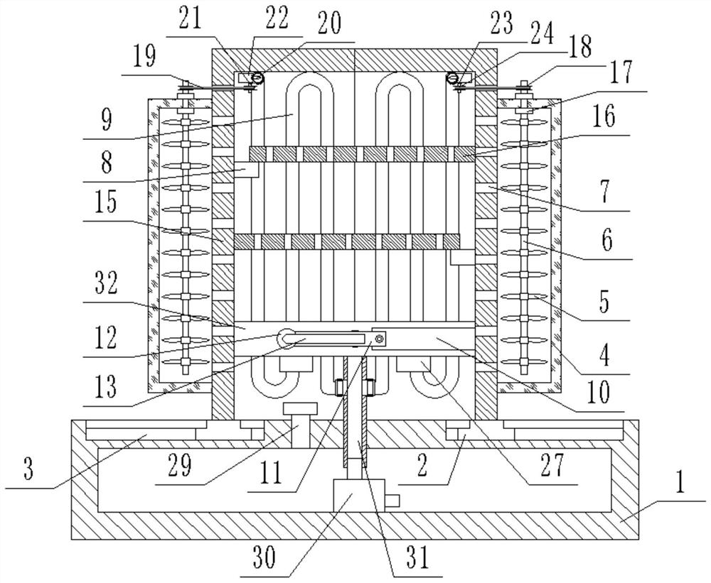
[0033] As shown in the picture- Figure 4 As shown, a server internal cooling device that is convenient for installing components includes a base box 1, the top of the base box 1 is fixedly connected with a fixed pipe 31 and communicated with it, and the top surface of the fixed pipe 31 is fixedly connected with a second A box body 32, the top surface of the second box body 32 is provided with a plurality of second through holes 14, a water pump 30 is fixedly connected to the base box 1, and the output end of the water pump 30 is fixedly connected to the fixed pipe 31, The top of the base box 1 on one side of the fixed pipe 31 is provided with a liquid filling port 29, and the liquid filling port 29 is connected to the base box 1, and the liquid filling port 29 is threadedly connected with a cover body. Two T-shaped chute 3 are symmetrically arranged o...


PUM


Abstract

The invention discloses a server internal cooling device convenient for element installation, which comprises a hollow base box connected with a second box body through a fixed pipe; the base box is communicated with the fixed pipe; two movable second cover bodies are symmetrically arranged on the base box with the fixed pipe as the axis. A corrugated guide pipe is arranged in each second cover body, one end of each corrugated guide pipe is communicated with the fixed pipe, and the other end is communicated with the base box; a water pump is arranged below the fixed pipe; at least one pore plate is arranged on the inner wall of each second cover body; a plurality of second through holes are formed in the top surface of the second box body, and at least one fan is arranged at the bottom; a third rotating rod is arranged on the second box body in a penetrating manner and is driven by a motor to rotate; one end of the third rotating rod is connected with one second cover body, and the other end is connected with the other second cover body; the third rotating rod rotates to drive the two second cover bodies to get close to and away from each other. Components are convenient to install, the installation and replacement process is simple, the internal temperature of the server body is reduced, the working efficiency of the server body is improved, and use requirements are met.

Description

technical field [0001] The invention relates to the field of server internal cooling devices, in particular to a server internal cooling device which is convenient for installing components. Background technique [0002] The composition of the server includes processors, hard disks, memory, system buses, etc., which are similar to general-purpose computer architectures, but due to the need to provide highly reliable services, processing power, stability, reliability, security, scalability, scalability The management requirements are high, and the dust prevention and heat dissipation of the server is also the most common problem. In daily work, the computer server will generate heat when it works for a long time. Failure to dissipate heat in time will reduce the working efficiency of the server. Existing servers usually dissipate heat through the cooling device carried by the server itself. In this way, the heat dissipation performance of the server is poor, and some of them ...

Claims


Application Information

Patent Timeline
Patent Type & Authority Applications(China)
IPC IPC(8): G06F1/20G06F1/18
CPCG06F1/20G06F1/181Y02D10/00
Inventor 阴冠林
Owner SUZHOU LANGCHAO INTELLIGENT TECH CO LTD
Learn More