Novel reinforcing structure for automobile longitudinal beam

A technology for automobile longitudinal beams and reinforced structures, which is applied in the field of automobile parts, can solve the problems of reducing production efficiency, inconvenience, and increasing production costs, and achieve the effects of improving reinforcement effects, reducing production costs, and improving practicability

Pending Publication Date: 2021-12-07
湖北智博伟业汽车部件有限公司
View PDF0 Cites 0 Cited by
  • Summary
  • Abstract
  • Description
  • Claims
  • Application Information

AI Technical Summary

Problems solved by technology

[0004] The purpose of the present invention is to provide a novel reinforcement structure for automobile longitudinal beams, to solve the problem that the existing automobile longitudinal beam reinforcement structures proposed in the above-mentioned background technology are fixed structures, and automobile longitudinal beams of different sizes need to produce different sizes. It will be very inconvenient to strengthen the structure for matching, which will reduce the production efficiency and increase the production cost.

Method used


Image

  • Novel reinforcing structure for automobile longitudinal beam
  • Novel reinforcing structure for automobile longitudinal beam
  • Novel reinforcing structure for automobile longitudinal beam

Examples


Embodiment 1

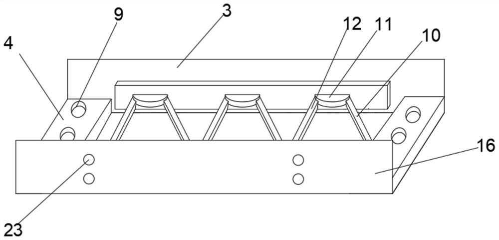
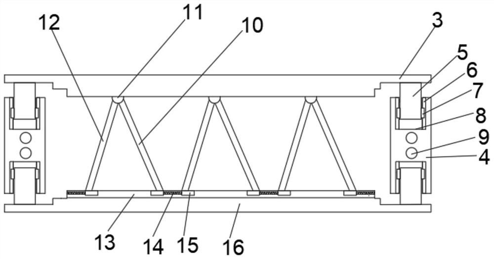
[0028] The number of the first rotating shafts 11 is three groups, and the three groups of the first rotating shafts 11 are evenly distributed on one side of the first mounting plate 3, and the second mounting plate 16 is opened on the side close to the first mounting plate 3 The second chute 13, the inner wall of the second chute 13 is slidably connected with the second slider 15, the number of the second slider 15 is six groups, and the six groups of the second slider 15 are evenly distributed on the second On the inner wall of the two chute 13, a spring 14 is arranged between each group of the second sliding blocks 15, and a first connecting rod 10 and a second connecting rod 12 are arranged on the outer wall of the first rotating shaft 11. The bottoms of the connecting rod 10 and the second connecting rod 12 are fixedly connected with the second sliding block 15, and the second sliding block 15 corresponds to the first connecting rod 10 and the second connecting rod 12. Wh...

Embodiment 2

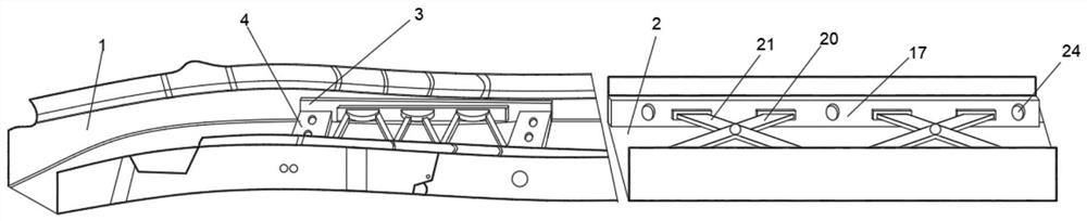
[0030]The inner wall of the rear section 2 of the longitudinal beam of the vehicle is provided with a third mounting plate 17, the number of the third mounting plates 17 is two groups, and the third mounting plates 17 of the two groups are symmetrically distributed on the rear section 2 of the longitudinal beam of the vehicle. On the inner wall, the sides of the third mounting plates 17 of the two groups are provided with draw-in slots 18, the number of the draw-in slots 18 is eight groups, and the eight sets of draw-in slots 18 are evenly distributed in the two groups of the third mounting plates. On the three mounting plates 17, the inner wall of the draw-in groove 18 is provided with a block 19, the surface of the third mounting plate 17 is hinged with a first movable rod 20, and the surface of another group of the third mounting plate 17 is hinged with The second movable rod 21, a second rotating shaft 22 is arranged between the first movable rod 20 and the second movable r...


PUM


Abstract

The invention discloses a novel reinforcing structure for an automobile longitudinal beam. The structure comprises an automobile longitudinal beam front section and an automobile longitudinal beam rear section, and a fixing block is arranged on the inner wall of the automobile longitudinal beam front section. When the automobile longitudinal beam front section needs to be reinforced, the fixing block is placed in the middle of the inner wall of the automobile longitudinal beam front section, then the fixing block and the automobile longitudinal beam front section are fixed through a formed first threaded hole, then a first mounting plate and a second mounting plate are pulled towards the two sides to drive a connecting block to move, and the connecting block drives a first sliding block to slide on the inner wall of a first sliding groove until the first mounting plate and the second mounting plate are attached to the inner wall of the front section of the automobile longitudinal beam; then the structure is fixed to the side inner wall of the front section of the automobile longitudinal beam through the formed second threaded hole, so that the structure can adapt to automobile longitudinal beams with different width sizes; and one structure is produced, so that the structure can adapt to automobile longitudinal beams of different sizes needing to be reinforced, the practicability of the device is improved, and the production cost is reduced.

Description

technical field [0001] The invention relates to the technical field of automobile parts, in particular to a novel reinforcement structure for automobile longitudinal beams. Background technique [0002] The frame is the most important load-bearing part in the car, and the frame longitudinal beam is one of the key parts, so the longitudinal beam plays an important role in the car, the side beam frame of the car, the middle beam car Frames, etc. contain stringers. Longitudinal beams are usually stamped from low-alloy steel plates, and the cross-sectional shape is generally groove-shaped, and some are made into Z-shaped or box-shaped cross-sections. [0003] The existing vehicle longitudinal beam reinforcement structure is a fixed structure, and different sizes of vehicle longitudinal beams need to produce different sizes of reinforcement structures for matching, which will be very inconvenient, reduce production efficiency, and also increase production costs. Contents of th...

Claims


Application Information

Patent Timeline
IPC IPC(8): B62D21/02B62D21/14
CPCB62D21/02B62D21/14Y02T10/40
Inventor 柴亚威李荣志杨昊储彦琦
Owner 湖北智博伟业汽车部件有限公司
Why Eureka
Try Eureka