
Electrically operated valve

A technology for electric valves and spools, which is applied in the direction of lift valves, valve devices, engine components, etc., and can solve the problem of increased gap between the spool 300 and the guide sleeve 200, axial deflection of the spool 300, and affecting the reliability of the electric valve action and other problems, to improve the reliability of the action and reduce the effect of wear

Pending Publication Date: 2021-12-10
ZHEJIANG SANHUA COMMERCIAL REFRIGERATION CO LTD
View PDF0 Cites 0 Cited by
  • Summary
  • Abstract
  • Description
  • Claims
  • Application Information

AI Technical Summary

Problems solved by technology

In this electric valve, when the spool 300 made of metal material reciprocates axially relative to the guide sleeve 200 made of metal material, the friction between the outer wall of the spool 300 and the inner wall of the guide sleeve 200 is two Due to the head-to-head friction between the metal surfaces, the outer wall of the spool 300 may be subject to greater friction and wear, so that the gap between the spool 300 and the guide sleeve 200 increases, resulting in the axial displacement of the spool 300 relative to the guide sleeve 200. Risk of deflection, which may affect the operating reliability of the electric valve

Method used


Image

  • Electrically operated valve
  • Electrically operated valve
  • Electrically operated valve

Examples


Embodiment Construction

[0023] It needs to be explained first that if the positional words used in this article, such as "upper" and "lower", are defined based on the positions shown in the drawings of the description herein, it should be understood that the use of the positional words is only For the sake of clarity and convenience in describing the technical solution, the scope of protection should not be limited.

[0024] In order to enable those skilled in the art to better understand the technical solution of the present application, the technical solution of the present application will be further described below in conjunction with the drawings and specific embodiments.

[0025] The limited connection in this article means that the two parts can be fixedly connected or not fixedly connected, and one of them can drive the other to move axially relative to the electric valve.

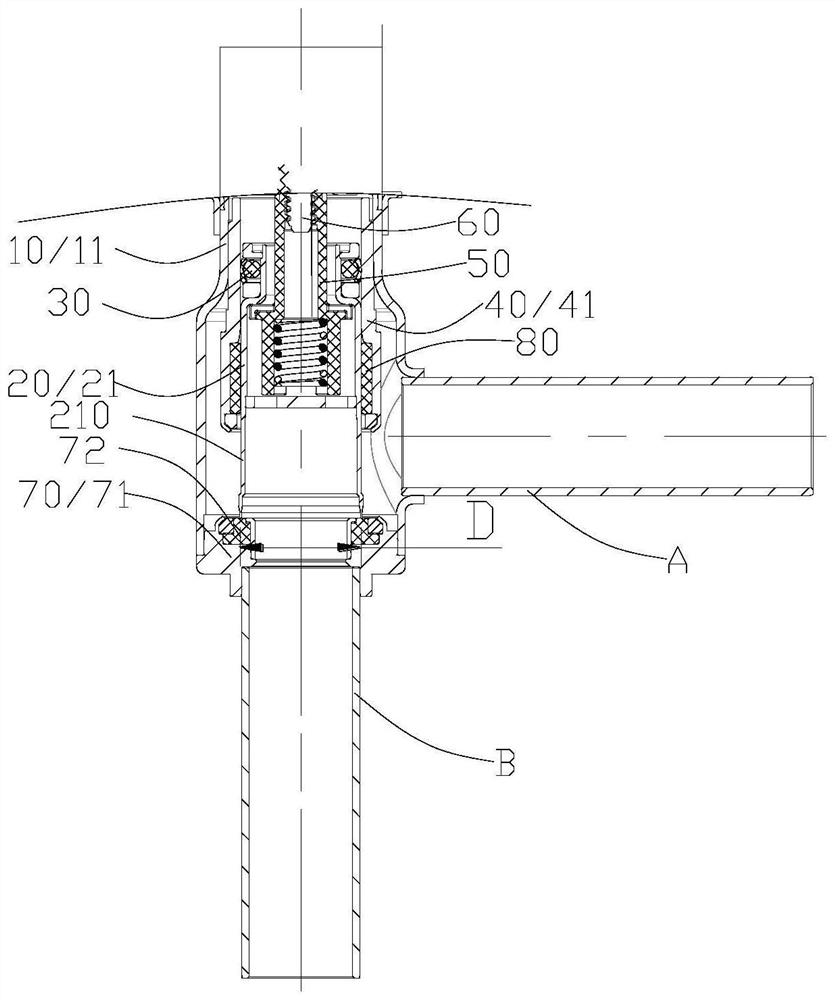
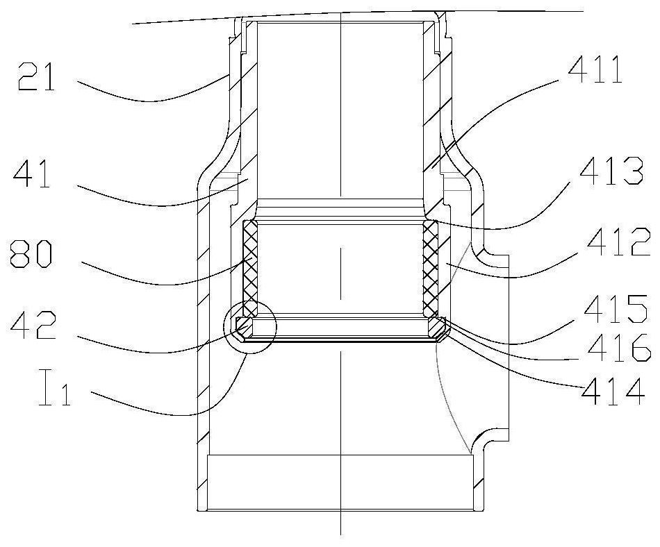
[0026] figure 2 Shown is a specific embodiment of the electric valve of the present invention - a schematic structura...


PUM


Abstract

The invention discloses an electrically operated valve. The valve comprises a valve body part, a valve element part, a sealing part and a sealing seat part, the sealing seat part comprises a sealing seat, the sealing seat is fixedly connected with the valve body part, the sealing part is arranged between the inner wall of the sealing seat and the outer wall of the valve element part, the valve element part comprises a valve element, a lining is arranged between the outer wall of the valve element and the inner wall of the sealing seat, the lining is connected with the sealing seat part in a limiting mode, the valve element can axially slide relative to the lining, the inner wall of the lining comprises a lubricating part made of non-metal materials, and the lubricating part can be matched with the valve element. The invention further discloses an electrically operated valve of another structure, and the action reliability of the electrically operated valve can be improved.

Description

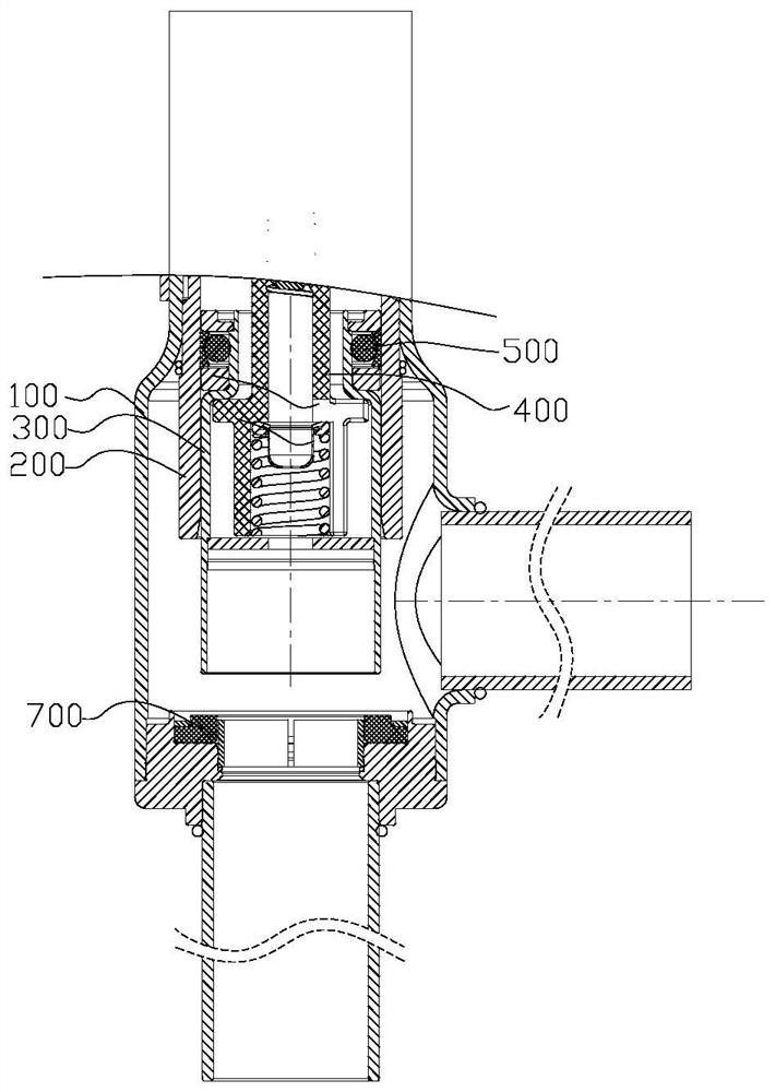
technical field [0001] The invention relates to the technical field of fluid control, in particular to an electric valve. Background technique [0002] figure 1 Shown is a partial structural schematic diagram of an electric valve in the background technology. The electric valve comprises a valve body 100, a guide sleeve 200 of a spool disposed in the valve body 100 and welded and fixed to the valve body 100, a spool 300 made of metal material, and a plastic nut 400. A sealing assembly 500 is provided, the part of the spool 300 located at the lower side of the sealing assembly 500 is slidingly fitted with the guide sleeve 200 , and the spool 300 can slide axially relative to the guide sleeve 200 driven by the nut 400 to abut against the seal 700 or separation. In this electric valve, when the spool 300 made of metal material reciprocates axially relative to the guide sleeve 200 made of metal material, the friction between the outer wall of the spool 300 and the inner wall ...

Claims


Application Information

Patent Timeline
Patent Type & Authority Applications(China)
IPC IPC(8): F16K1/02F16K1/32F16K1/36F16K1/42F16K1/46F16K29/00
CPCF16K1/02F16K1/32F16K1/36F16K1/42F16K1/465F16K29/00
Inventor 不公告发明人
Owner ZHEJIANG SANHUA COMMERCIAL REFRIGERATION CO LTD
Learn More