Intelligent lock with straight handle

A technology of smart lock and straight handle, applied in the field of locks, can solve the problems of not being compact and neat, and the area of ​​the lock body being large.

Pending Publication Date: 2020-01-03
广东摩力智能科技有限公司
View PDF0 Cites 0 Cited by
  • Summary
  • Abstract
  • Description
  • Claims
  • Application Information

AI Technical Summary

Problems solved by technology

[0002] In the existing straight handle smart lock, the touch panel is separated from the handle, or only fingerprint recognition is on the handle, and the mechanical lock structure is on the connecting shaft between the handle and the base. Accommodating the lock head results in an elliptical cylinder, which is not compact and neat enough

Method used


Image

  • Intelligent lock with straight handle
  • Intelligent lock with straight handle
  • Intelligent lock with straight handle

Examples


Embodiment 1

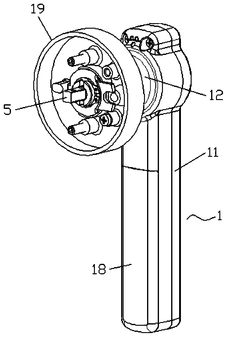
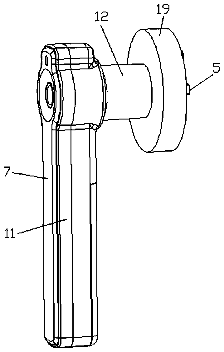
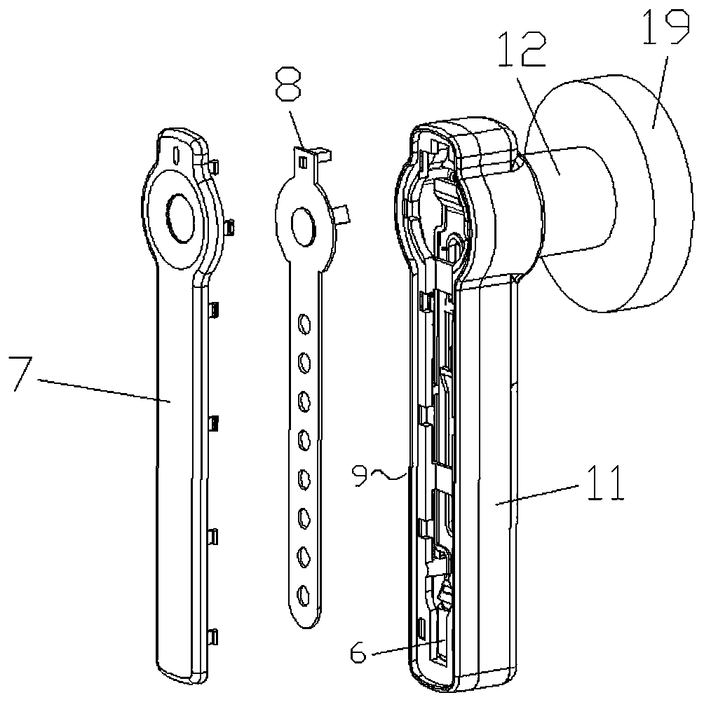
[0030] Such as Figure 1-Figure 7 As shown, the straight-handle smart lock of the present application includes a handle 1, a motor reset mechanism 2, a connecting shaft 3, a fixing seat 4, a handle 5, a lock 6, a touch panel 7 and a circuit board 8; the grip of the handle 1 The holding portion 11 and the bending portion 12 are provided with a communicating cavity, the motor implementing reset mechanism 2 is installed in the cavity of the bending portion 12, the connecting shaft 3 is slidingly mounted on the motor implementing reset mechanism 2, and the connecting shaft 3 The sliding direction is consistent with the axial direction of the connecting shaft 3. The fixed seat 4 is installed on the motor reset mechanism 2, the handle 5 is rotated and installed on the fixed seat 4, the handle 5 passes through the bending part 12, and the fixed seat 4 is provided with In the through hole 41 through which the connecting shaft 3 passes, a connecting groove 51 is provided on the handle 5...

Embodiment 2

[0037] The straight handle smart lock provided in the second embodiment is a further improvement of the straight handle smart lock provided in the first embodiment. Figure 1-Figure 7 On the basis of the second embodiment, the straight handle smart lock provided in the second embodiment further includes a connecting shaft guide plate 16, which is installed in the cavity of the holding portion 11, and the connecting shaft 3 passes through the connecting shaft guide plate 16 and the pressing plate 9 Abutment connection.

[0038] The connecting shaft guide plate 16 guides the movement direction of the connecting shaft 3 to prevent the movement of the connecting shaft 3 from shifting.

[0039] Specifically, the handle 5 includes a handle cover 52 and a handle body 53. The handle body 53 is elongated. One end of the handle body 53 is connected to the handle cover 52. The handle cover 52 is provided with a connecting groove 51 for fixing The seat 4 is provided with a connecting hole 42,...


PUM


Abstract

The invention relates to an intelligent lock with a straight handle. The intelligent lock comprises a handle, a motor executed resetting mechanism, a connecting shaft, a fixed seat, a handling head, alocking head, a touch panel and a circuit board. Communicating cavities are formed in a holding part and a bending part of the handle, the motor executed resetting mechanism is mounted in the cavityof the bending part, the connecting shaft is slidably mounted on the motor executed resetting mechanism, a fixed seat is mounted on the motor executed resetting mechanism, the handling head is rotatably mounted on the fixed seat, a through hole where the connecting shaft penetrates is formed in the fixed seat, a connecting slot is formed in a position, corresponding to the through hole, in the handing head, a pressing plate in leaning connection to the connecting shaft is slidably mounted in the cavity of the holding part, the locking head is mounted on the end tail part of the cavity of the holding part, the locking head is connected to the pressing plate through a locking head cap, the touch panel is mounted on the front end surface of the holding part, the circuit board is mounted in the cavity of the holding part, and the circuit board is separately connected to the touch panel and the motor executed resetting mechanism. By means of the arrangement, the intelligent lock is compactin structure and the action reliability of the connecting shaft is good.

Description

Technical field [0001] The invention relates to a lock, in particular to a straight handle intelligent lock. Background technique [0002] In the existing straight-handle smart lock, the touchpad is separated from the handle, or only fingerprint recognition is on the handle, and the mechanical lock structure is on the connecting shaft between the handle and the base. This kind of arrangement occupies a large area of ​​the lock body, or the connection is The lock head is accommodated, resulting in an elliptical cylinder, which is not compact and neat. Summary of the invention [0003] The purpose of the present invention is to provide a straight handle intelligent lock to solve the above-mentioned problems in the prior art. [0004] In order to achieve the above objectives of the present invention, the following technical solutions are adopted: [0005] A straight handle smart lock, which is characterized in that it comprises a handle, a motor reset mechanism, a connecting shaft, a f...

Claims


Application Information

Patent Timeline
Patent Type & Authority Applications(China)
IPC IPC(8): E05B47/00E05B3/00E05B15/00E05B1/00
CPCE05B1/003E05B1/0084E05B3/00E05B15/00E05B47/0001E05B47/0012E05B2047/0058
Inventor 相启正相鸿
Owner 广东摩力智能科技有限公司
Why Eureka
Try Eureka