Electric control valve

A technology for electric control valves and valve bodies, which is applied in the direction of electric components, valve devices, valve details, etc., and can solve problems affecting the reliability of electric control valves.

Pending Publication Date: 2022-03-04
ZHEJIANG SANHUA COMMERCIAL REFRIGERATION CO LTD
View PDF0 Cites 0 Cited by
  • Summary
  • Abstract
  • Description
  • Claims
  • Application Information

AI Technical Summary

Problems solved by technology

The fixing nut 01 is threadedly connected to the valve body 02, and the pin 03 is electrically connected to the wiring part 06 and the terminal 04. When the electric control valve is applied, the fluid outside the electric control valve, such as water, enters between the joint 01 and the valve body 02. The hidden danger that affects the reliability of the electrical connection between the wiring part 06 and the pin 03, and affects the operation reliability of the electric control valve

Method used


Image

  • Electric control valve
  • Electric control valve
  • Electric control valve

Examples


Embodiment Construction

[0024] It needs to be explained first that if the orientation words used in this article, such as "up" and "down", are all defined based on the positions shown in the drawings in this specification, it should be understood that the use of the orientation words is only for The clarity and convenience of describing the technical solution should not limit the scope of protection.

[0025] In order to enable those skilled in the art to better understand the technical solution of the present application, the technical solution of the present application will be further described below in conjunction with the drawings and specific embodiments.

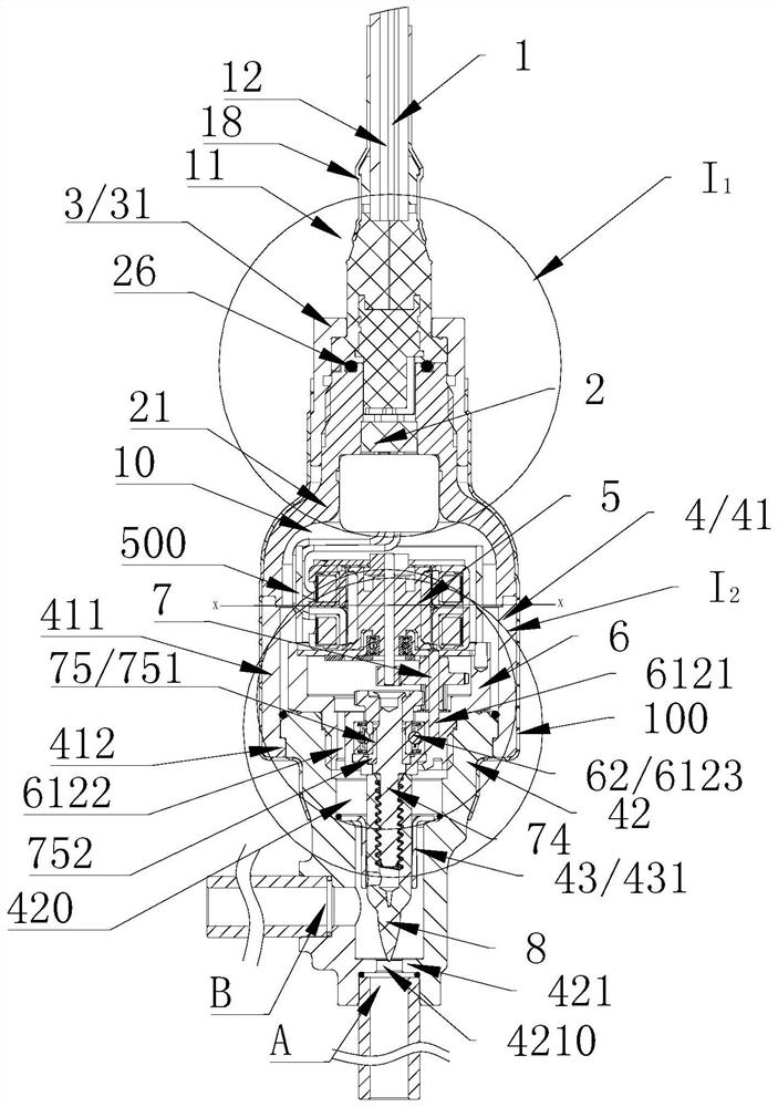
[0026] Such as figure 2 As shown, the electric control valve includes a lead assembly 1 , a glass seat assembly 2 , a fixing nut 3 , a valve body assembly 4 , a motor assembly 5 , a support seat assembly 6 , a transmission assembly 7 and a valve core assembly 8 .

[0027] The valve body assembly 4 is fixedly connected with the glass seat a...


PUM


Abstract

The invention discloses an electric control valve which comprises a valve body assembly, a glass base assembly, a lead assembly and a fixing nut, the glass base assembly comprises a shell, a glass base and a glass base contact pin, the glass base is fixedly connected with the shell, the glass base contact pin is fixedly connected with the glass base, and the lead assembly is fixedly connected with the shell. The shell is fixedly connected with the valve body assembly; the lead assembly comprises a connecting body, a protective sleeve and a connecting body contact pin, the protective sleeve is fixedly connected with the connecting body, the connecting body contact pin is fixedly connected with the connecting body, and the connecting body contact pin is electrically connected with the glass base contact pin; the fixing nut comprises a sleeve part and a pressing part, the sleeve part is in threaded connection with the shell, the pressing part is connected with the protective sleeve in a sleeved mode, one of the pressing part and the protective sleeve comprises an annular sealing convex rib, and the sealing convex rib abuts against the other one of the pressing part and the protective sleeve. The operation reliability of the electric control valve is improved.

Description

technical field [0001] The invention relates to the technical field of fluid control, in particular to an electric control valve. Background technique [0002] figure 1 Shown is a partial structural schematic diagram of an electric control valve in the background technology. The electric control valve includes a valve body 02, a joint 01, a wiring part 06, a pin 03, a motor 05, and a terminal 04 of the motor 05. The fixing nut 01 is threadedly connected with the valve body 02, and the pin 03 is electrically connected with the wiring part 06 and the terminal 04. When the electric control valve is applied, the fluid outside the electric control valve, such as water, enters between the joint 01 and the valve body 02. The hidden danger that affects the reliability of the electrical connection between the wiring part 06 and the pin 03, and affects the operation reliability of the electric control valve. Contents of the invention [0003] The purpose of this application is to...

Claims


Application Information

Patent Timeline
Patent Type & Authority Applications(China)
IPC IPC(8): F16K31/04H02K5/22
CPCF16K31/04H02K5/22H02K5/225
Inventor 不公告发明人
Owner ZHEJIANG SANHUA COMMERCIAL REFRIGERATION CO LTD
Why Eureka
Try Eureka