
Unmanned aerial vehicle coverage path planning method based on three-dimensional model

A 3D model and coverage path technology, applied in the field of UAVs, can solve the problem of being unable to evaluate the full coverage of UAV flight routes, and achieve the effect of reducing costs and improving detection efficiency

Active Publication Date: 2021-12-10
NANJING UNIV OF AERONAUTICS & ASTRONAUTICS
View PDF7 Cites 1 Cited by
  • Summary
  • Abstract
  • Description
  • Claims
  • Application Information

AI Technical Summary

Problems solved by technology

However, the use of a handheld remote control to control the UAV to fly on the ground makes it impossible to evaluate whether the UAV flight route has achieved full coverage

Method used


Image

  • Unmanned aerial vehicle coverage path planning method based on three-dimensional model
  • Unmanned aerial vehicle coverage path planning method based on three-dimensional model
  • Unmanned aerial vehicle coverage path planning method based on three-dimensional model

Examples


Embodiment Construction

[0042] The present invention is further illustrated in conjunction with the description.

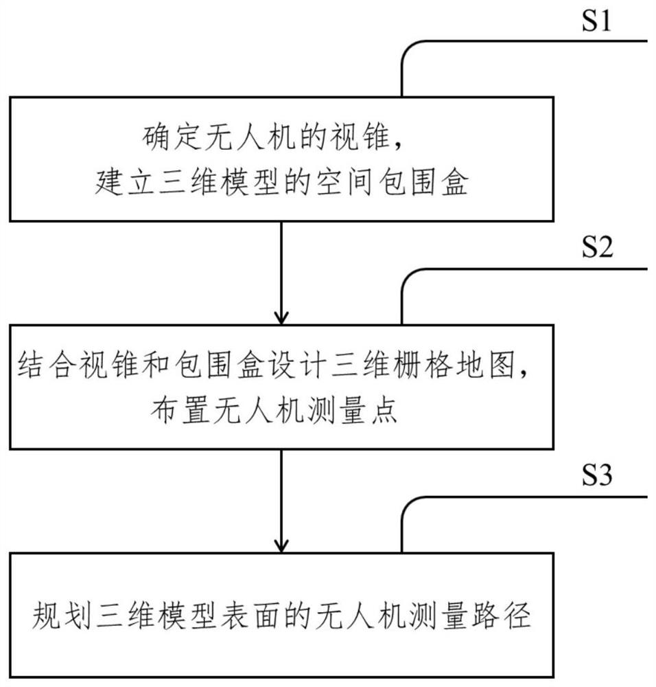
[0043] The present invention provides a modification of a large flexible body deformation monitoring device and method, as an example, such as figure 1 As shown, including the following steps:

[0044] S1: Determine the cone size of the drone, establish a space envelopment box for the three-dimensional model;

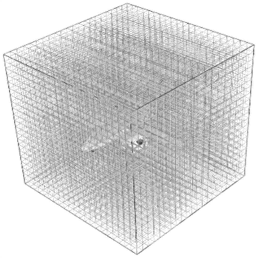
[0045] S2: Combined with cone and envelopes design three-dimensional grid map, arranged drone measurement points;

[0046] S3: Plan the drone measurement path of the three-dimensional model surface.

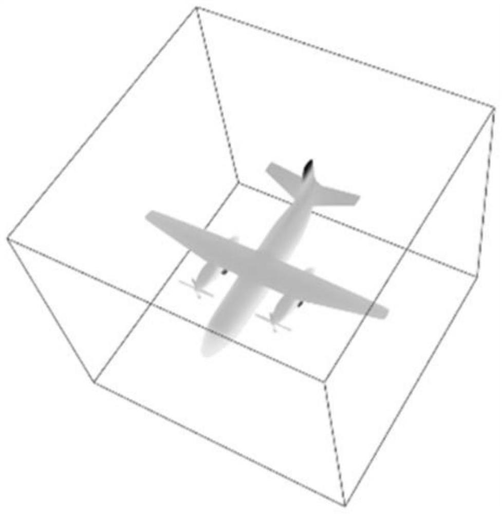
[0047] Further, it is determined that the disconvel cone size, establishes a space envelope of the three-dimensional model, including the following steps:

[0048] S11: Defines the cone size of the drone to ensure that the working distance of the drone's cone is constituted by a cubic unit, defining the cubic unit edge length L.

[0049] S12: Calculate the maximum value of each of the th...


PUM


Abstract

The invention discloses an unmanned aerial vehicle coverage path planning method based on a three-dimensional model, and the method comprises the following steps: determining the size of a view cone of an unmanned aerial vehicle, and building a space bounding box of the three-dimensional model; designing a three-dimensional grid map by combining a visual cone and a bounding box, defining attributes of grids, and arranging unmanned aerial vehicle measurement points on the surface of the three-dimensional model; and planning an unmanned aerial vehicle measurement path on the surface of the three-dimensional model according to the measurement points. According to the unmanned aerial vehicle coverage path planning method based on the three-dimensional model, the detection time can be effectively shortened, meanwhile, the safety between the unmanned aerial vehicle and the three-dimensional object is guaranteed, and missing-free detection of the surface of the three-dimensional object is achieved.

Description

Technical field [0001] The present invention relates to the field of drone, and in particular, to a process of drone coverage path planning based on three-dimensional model. Background technique [0002] In recent years, the drone has been widely used in various fields due to its flexible and lightweight and low cost advantages, and the introduction of drone effectively reduces costs in the surface test task of the aircraft. The traditional aircraft surface detection task requires the staff to visually detect the surface of the aircraft, or combined with litting platforms and cranes to achieve the surface detection of the aircraft body body. The surface testing scheme based on the drone reduces the cost of labor and improves time efficiency. [0003] The existing drone path planning method is realized by two-dimensional maps. However, the surface testing of the aircraft is the application scenario with three-dimensional space. It is necessary to adjust the flight height as requir...

Claims


Application Information

Patent Timeline
Patent Type & Authority Applications(China)
IPC IPC(8): G05D1/10
CPCG05D1/101G05D1/0094G06T17/10G06T2210/12G06T17/05B64U2201/10B64U2101/26
Inventor 汪俊戴佳佳
Owner NANJING UNIV OF AERONAUTICS & ASTRONAUTICS
Learn More