Supercharge Your Innovation With Domain-Expert AI Agents!

Molten steel furnace

A molten steel furnace and water furnace technology, which is used in casting molten material containers, metal processing equipment, casting equipment, etc., can solve the problems of easy turning, power consumption, inconvenient unloading of the molten steel furnace, etc., and achieves improved stability and stability. high effect

Pending Publication Date: 2021-12-17
浦惠新材料科技江苏有限公司
View PDF7 Cites 0 Cited by
  • Summary
  • Abstract
  • Description
  • Claims
  • Application Information

AI Technical Summary

Problems solved by technology

[0003] The existing technology has the following disadvantages: the existing molten steel furnace directly operates the machine to control the rotation of the molten steel furnace when pouring molten steel. Due to the heavy weight of the molte

Method used


Image

  • Molten steel furnace
  • Molten steel furnace
  • Molten steel furnace

Examples


Embodiment 1

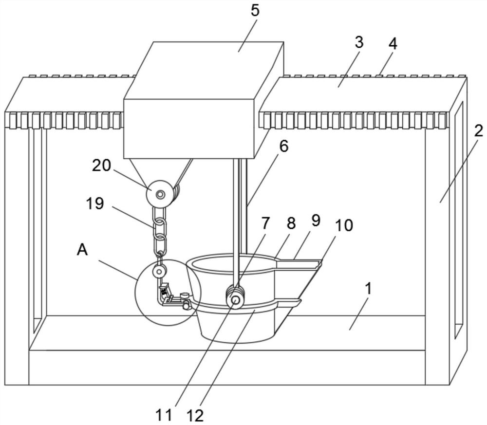
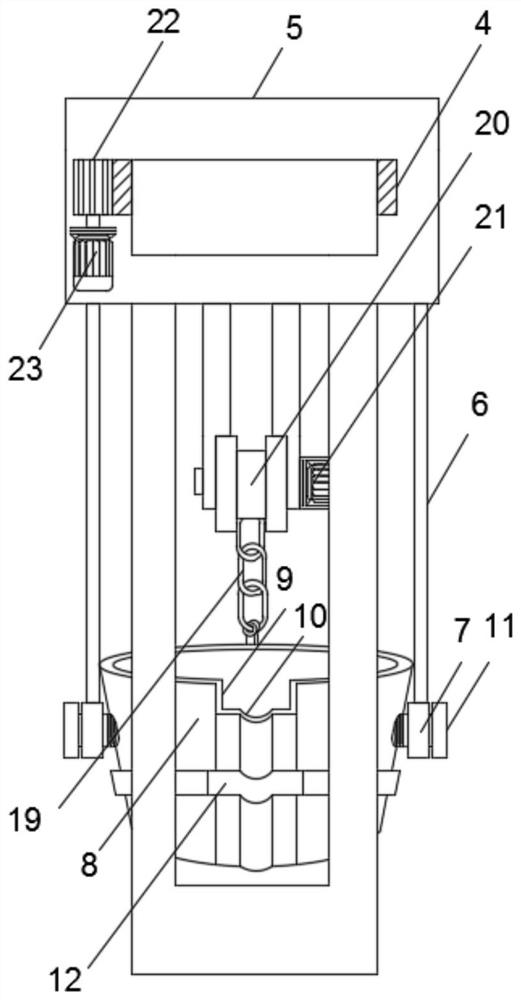
[0032] Refer to attached Figure 1-Figure 4 , a molten steel furnace in this embodiment, comprising a conveying device body 1, a slider 5, a molten steel furnace 8 and a conveying device two body 25, a supporting plate 2 is installed on the top of the conveying device body 1, and the top of the supporting plate 2 is fixedly connected to a sliding track 3 , a rack 4 is installed on one side of the support plate 2, a slider 5 is sleeved on the outer surface of the sliding track 3, a suspension rod 6 is installed on the bottom of the slider 5, the bottom end of the suspension rod 6 is fixedly connected to the collar 7, and the molten steel furnace 8 is installed on one side There is a pouring port 9, and the top of the pouring port 9 is provided with an arc-shaped slot 10. The outer surface of the molten steel furnace 8 is sleeved with a side surround 12, and a hole rivet 13 is installed on one side of the side surround 12, and the inner wall of the hole rivet 13 is socketed with ...

Embodiment 2

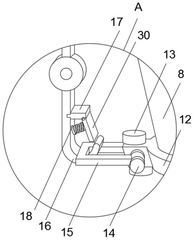
[0041] Refer to attached Figure 5-Figure 6 , a kind of molten steel furnace of this embodiment, comprises, concretely, conveying device two body 25 comprises wide steel hook 16, and wide steel hook 16 side is equipped with linear motor 26, and wide steel hook 16 side outer surface is provided with sliding groove 28 , the output end of the linear motor 26 is equipped with a telescopic rod 27, and the telescopic rod 27 is slidably connected in the sliding groove 28 and is fixedly connected with the rotating clamp plate 30 with a pin shaft, and is driven by the staff linear motor 26 to slide and push to the right in the sliding groove 28 Rotate the clamping plate 30 with the pin shaft, and put down the hinge 19, so that the wide steel hook 16 moves downward, and take out the wide steel hook 16, then by turning the fixing screw 11, remove the rotating rings 15 on both sides, and finally hang it by a crane. Lower molten steel furnace 8, reach the effect of unloading molten steel f...


PUM


Abstract

The invention discloses a molten steel furnace, and specifically relates to the technical field of steelmaking process. The technical scheme is as follows: the molten steel furnace comprises a conveying device body, a sliding device, a molten steel furnace body and a second conveying device body, wherein a supporting plate is installed at the top of the conveying device body, a sliding rail is fixedly connected to the top of the supporting plate, and a rack is installed at one side of the supporting plate; and the outer surface of the sliding rail is connected with the sliding device in a sleeving mode, a hanging rod is installed at the bottom of the sliding device, the bottom end of the hanging rod is fixedly connected with a lantern ring, a pouring port is formed in one side of the molten steel furnace body, and an arc-shaped open groove is formed in the top of the pouring port. The molten steel furnace has the beneficial effects of being high in stability and energy-saving, convenient in molten steel conveying and molten steel pouring, and convenient to detach or replace.

Description

technical field [0001] The invention relates to the technical field of steelmaking technology, in particular to a molten steel furnace. Background technique [0002] Extra-furnace refining refers to the metallurgical process of moving the molten steel that has been smelted in a converter, open hearth furnace or electric furnace to another container for refining, also known as "ladle metallurgy" or "secondary metallurgy", that is, the traditional steelmaking The process is divided into two steps: primary smelting and refining. During primary smelting, the charge is melted, dephosphorized, desulfurized, impurity removed and main alloyed in a furnace with an oxidative atmosphere to obtain primary molten steel. The molten steel is degassed, deoxidized, desulfurized, removed inclusions and fine-tuned in composition in a vacuum, inert gas or reducing atmosphere container. The implementation of extra-furnace refining can improve the quality of steel, shorten the smelting time, opt...

Claims


Application Information

Patent Timeline
IPC IPC(8): B22D41/12B22D41/06
CPCB22D41/12B22D41/06
Inventor 浦进王念东浦杰
Owner 浦惠新材料科技江苏有限公司
Features
  • R&D
  • Intellectual Property
  • Life Sciences
  • Materials
  • Tech Scout
  • Unparalleled Data Quality
  • Higher Quality Content
  • 60% Fewer Hallucinations
Learn More