Expansion joint suitable for low-clearance lightweight busbar

A technology of expansion joints and busbars, applied in the direction of overhead lines, etc., can solve the problems of rigid catenary suspension structure rigidity, rigid catenary contact wire wear, affecting pantograph-catenary contact and current intake, etc., to ensure good current intake, Improve followability and small structure height

Pending Publication Date: 2021-12-21
中铁建电气化局集团轨道交通器材有限公司
View PDF0 Cites 0 Cited by
  • Summary
  • Abstract
  • Description
  • Claims
  • Application Information

AI Technical Summary

Problems solved by technology

[0004] The rigid catenary suspension structure is relatively rigid, and the pantograph will be impacted when it passes through the rigid anchor point at high speed, especially at the joint of the anchor section, which is not conducive to good pantograph-catenary dynamic flow; the rigidity of the anchor point causes rigidity The serious and uneven wear of catenary contact wires is more prominent, which affects the normal contact and flow between the pantograph and catenary, thereby affecting the operation safety; the expansion joint of the busbar is connected in series between the busbars of the two anchor sections. increase, the contact force of the pantograph changes suddenly, thus forming a hard point between the pantograph and catenary, and the hard point causes the pantograph and catenary to go offline and the high-temperature arc generated at the moment of offline, which brings great harm to the catenary and pantograph

Method used


Image

  • Expansion joint suitable for low-clearance lightweight busbar
  • Expansion joint suitable for low-clearance lightweight busbar
  • Expansion joint suitable for low-clearance lightweight busbar

Examples


Embodiment Construction

[0030] The present invention will now be described in further detail with reference to the accompanying drawings. These drawings are all simplified schematic diagrams, and only illustrate the basic structure of the present invention in a schematic manner, so they only show the structures related to the present invention.

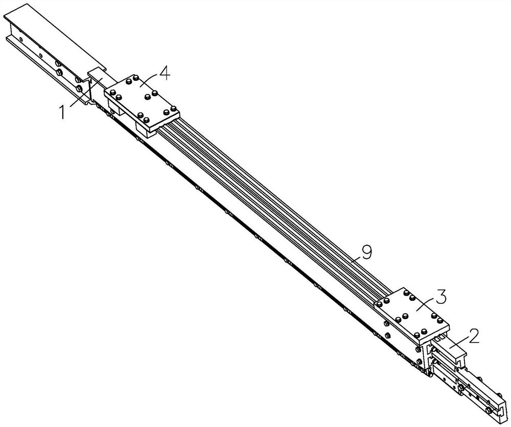
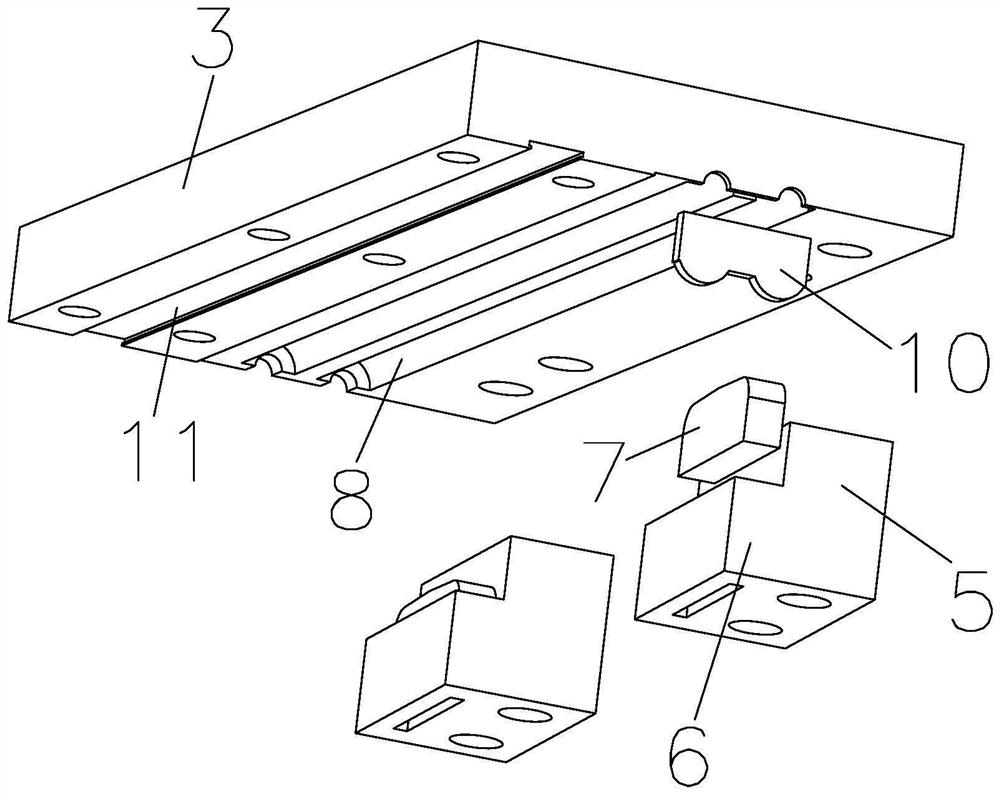
[0031] like Figure 1-2 As shown, the present invention is an expansion joint suitable for low headroom lightweight busbars, comprising: two first expansion joints 1 and second expansion joints 2 arranged in parallel; The joint 1 is fixedly connected, and the bottom of the other end is fixedly provided with a lower pressure plate 5; the second flow collector 4 is fixedly connected with the second expansion joint 2 at one end, and the bottom of the other end is fixed with a lower pressure plate 5; the lower pressure plate 5 has a horizontal setting The horizontal section 6 is provided with a groove on the horizontal section 6, and a pressure block 7 whose to...


PUM


Abstract

The invention relates to an expansion joint suitable for a low-clearance lightweight busbar. The expansion joint comprises a first expansion joint and a second expansion joint which are arranged in parallel, wherein one end of the first flow taking device is fixedly connected with the first expansion joint, and a lower pressing plate is fixedly arranged at the bottom of the other end; one end of the second flow taking device is fixedly connected with the second expansion joint, and a lower pressing plate is fixedly arranged at the bottom of the other end; the lower pressing plate is provided with a horizontal section which is horizontally arranged, a groove is formed in the horizontal section, and a pressing block with the top abutting against the bottom of the second expansion joint or the first expansion joint is installed in the groove; the pressing block is matched with the bottom of the flow taking device to clamp the second expansion joint or the first expansion joint, and the first flow taking device is in sliding connection with the second expansion joint or the second flow taking device is in sliding connection with the first expansion joint; the first expansion joint can slide relative to the second expansion joint, stable operation of the locomotive is guaranteed, and safety and reliability of operation of the locomotive are improved.

Description

technical field [0001] The invention relates to an expansion joint, in particular to an expansion joint suitable for low headroom and lightweight busbars. Background technique [0002] Urban rail transit is restricted by topography, urban planning and other conditions. The urban area is mostly underground. The catenary in the underground tunnel mainly adopts rigid suspension, and its structural height is limited by the clearance of the tunnel; in actual engineering, the rigid catenary suspension system The components and parts must not only meet the clearance requirements of the tunnel, but also ensure safe and reliable power supply; therefore, the development of busbar expansion joints suitable for low-clearance tunnel environments is the future development trend of rigid catenary. [0003] The ideal operating state of the rigid suspension power supply system is that the contact between the pantograph and catenary is reliable, which provides guarantee for the electric locom...

Claims


Application Information

Patent Timeline
Patent Type & Authority Applications(China)
IPC IPC(8): B60M1/24
CPCB60M1/24
Inventor 冯晓河王涛熊星宋博瀚陆佳张琳孙硕谢峰崔浩峰张敏郭建华葛志锐崔华新
Owner 中铁建电气化局集团轨道交通器材有限公司
Why Eureka
Try Eureka