Rotor wing propelling device and control method
A propulsion device and rotor technology, applied in the aviation field, can solve problems such as complex structures and complex control methods of aircraft, and achieve the effects of reliable transmission structure, reduced complexity, and low manufacturing cost
- Summary
- Abstract
- Description
- Claims
- Application Information
AI Technical Summary
Problems solved by technology
Method used
Image
Examples
Embodiment 1
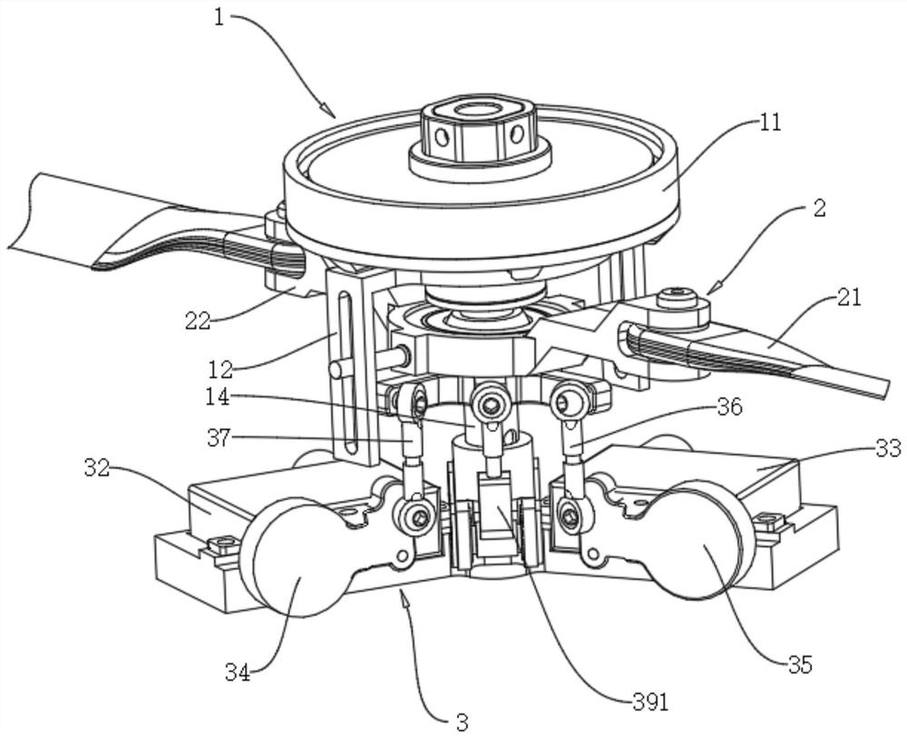
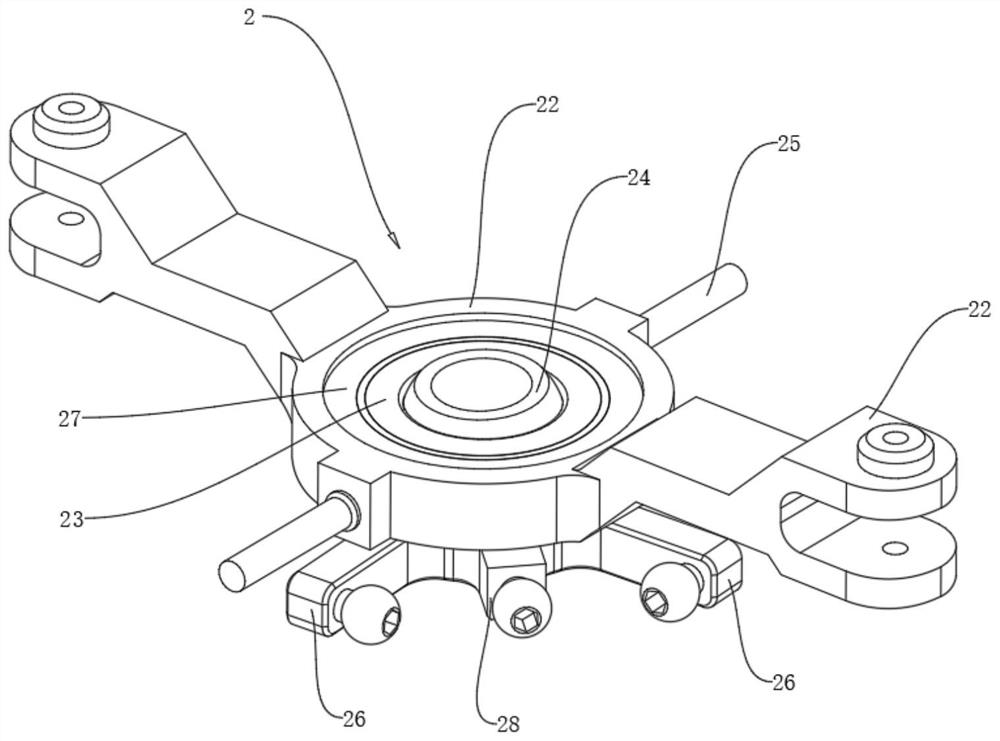
[0035] Such as Figure 1-Figure 2 As shown, this embodiment discloses a rotor propulsion device, which includes an upper power mechanism 1 , a central axis tilt drive assembly 3 and an upper vector tilt rotor assembly 2 .
[0036]The upper power mechanism 1 includes an upper drive module 11, an upper fixed central shaft 13, and an upper rotor drive slide rail 12; the upper drive module 11 is arranged on the upper end of the upper fixed central shaft 13, and the upper drive module 11 is connected with the upper rotor drive slide rail 12 It is used to drive the upper rotor drive slide rail 12 to rotate around the upper fixed central axis 13 . The upper drive module 11 can be a direct-drive brushless motor, a brushless motor and gearbox, or a fuel engine. In this embodiment, the upper drive module 11 uses a direct-drive brushless motor. The stator is fixedly connected with the upper fixed center shaft 13, and the rotor of the direct-drive brushless motor is connected with the up...
Embodiment 2
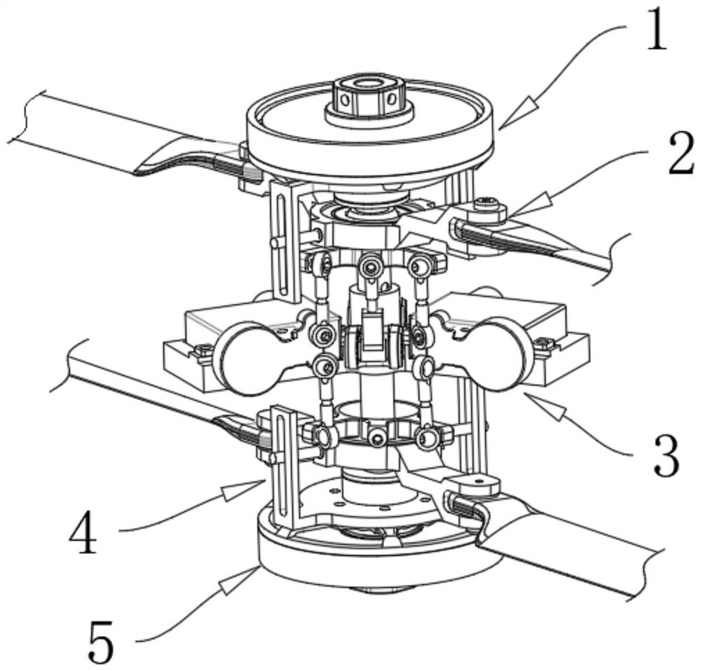
[0047] Such as Figure 2-6 As shown, this embodiment discloses a coaxial double-rotor propulsion device. Compared with the rotor propulsion device in Embodiment 1, this embodiment is equivalent to two symmetrically distributed rotor propulsion devices in Embodiment 1. Through two The rotor propulsion devices work together, and the two rotor propulsion devices share the No. 1 driver 32 and the No. 2 driver 33. The specific structure is as follows:
[0048] A coaxial double-rotor propulsion device includes an upper power mechanism 1 , a center axis tilt drive assembly 3 , an upper vector tilt rotor assembly 2 , a lower power mechanism 5 and a lower vector tilt rotor assembly 4 .
[0049] The upper power mechanism 1 includes an upper drive module 11, an upper fixed central shaft 13, and an upper rotor drive slide rail 12; the upper drive module 11 is arranged on the upper end of the upper fixed central shaft 13, and the upper drive module 11 is connected with the upper rotor driv...
Embodiment 3
[0063] refer to Figure 7 , this embodiment discloses a coaxial twin-rotor helicopter, comprising a fuselage 6 and a coaxial twin-rotor propulsion device arranged above the fuselage 6, the coaxial twin-rotor propulsion device being the coaxial twin-rotor propulsion device in Embodiment 2 device.
[0064] A control method of a coaxial twin-rotor helicopter disclosed in this embodiment is as follows:
[0065] The heading of the aircraft is controlled by adjusting the rotational speed difference of the upper and lower rotors, and the tilt angles of the upper vector tilt rotor assembly 2 and the lower vector tilt rotor assembly 4 are controlled by the No. 1 driver 32 and the No. 2 driver 33 to adjust the lift direction generated by the paddle disc , so as to control the rolling and pitching motion of the aircraft;
[0066] By accelerating or decelerating the up and down rotors at the same time, adjust the lift of the aircraft.
PUM
 Abstract
Description
Claims
Application Information
 - R&D
- Intellectual Property
- Life Sciences
- Materials
- Tech Scout
- Unparalleled Data Quality
- Higher Quality Content
- 60% Fewer Hallucinations
Browse by: Latest US Patents, China's latest patents, Technical Efficacy Thesaurus, Application Domain, Technology Topic, Popular Technical Reports.
© 2025 PatSnap. All rights reserved.Legal|Privacy policy|Modern Slavery Act Transparency Statement|Sitemap|About US| Contact US: help@patsnap.com


