Teaching demonstration equipment for electronic computer software development
An electronic computer and software development technology, which is applied in computing, computer display casing, electrical digital data processing, etc., can solve the problem of sensitivity reduction and achieve the effect of improving fluency and avoiding touch sensitivity
- Summary
- Abstract
- Description
- Claims
- Application Information
AI Technical Summary
Problems solved by technology
Method used
Image

Examples
Embodiment 1
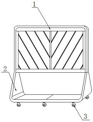
[0030] as attached figure 1 to attach Figure 6 Shown:
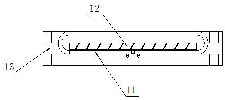
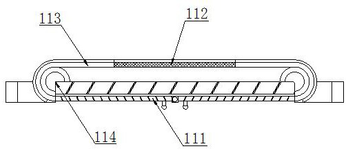
[0031] Its structure includes an equipment table 1, a support frame 2, and sliding wheels 3. The bottom of the equipment table 1 is embedded and connected with the top of the support frame 2, the bottom of the support frame 2 is spirally connected with the top of the sliding wheel 3, and the upper end of the sliding wheel 3 Cooperate with the overall clearance of the equipment table 1, the equipment table 1 includes an airtight cover 11, a demonstration frame 12, and a table body 13, the bottom of the table body 13 is embedded and connected with the top of the support frame 2, and the inner wall of the airtight cover 11 is connected to the demonstration frame 12, the outer wall is embedded and connected, and the demonstration frame 12 is integrally fitted with the internal clearance of the table body 13, and the inner surface of the table body 13 is embedded and connected with the outer wall of the airtight cover 11.
...
Embodiment 2
[0039] as attached Figure 7 to attach Figure 9 Shown:
[0040] Wherein, the demonstration stand 12 includes an all-in-one machine 121, a display screen frame 122, and a radiator 123. The all-in-one machine 121 is integrally matched with the surface of the platform body 13, and the outer wall of the all-in-one machine 121 is embedded and connected with the inner wall of the airtight cover 11. The surface of the all-in-one machine 121 is engaged with the surroundings of the display screen frame 122, and the inner side of the display screen frame 122 is positively matched with the radiator 123. Both ends of the radiator 123 are bolted to the back end of the all-in-one machine 121. The radiator 123 is composed of three cooling fans. The cooling fan in the middle is used as a suction fan, and the left and right sides are exhaust fans. The two ends of the radiator 123 are fixed to the back of the all-in-one machine 121 with bolts. The internal heat circulation enables the extern...
PUM
 Abstract
Description
Claims
Application Information
PatSnap Eureka turns technology decisions into work you can execute. Powered by our Innovation Knowledge Graph, it runs expert workflows across engineering, life sciences, materials and intellectual property. Get your review-ready output in minutes.


