
Cutter polishing equipment capable of simultaneously polishing double sides

A kind of equipment and double-sided technology, applied in the direction of grinding/polishing equipment, metal processing equipment, other manufacturing equipment/tools, etc., can solve the problems of impossible sharpening, poor user experience, complex structure, etc., and improve the sharpening effect , reduce sharpening time, low cost effect

Pending Publication Date: 2021-12-28
余姚市诺顿电器有限公司
View PDF7 Cites 1 Cited by
  • Summary
  • Abstract
  • Description
  • Claims
  • Application Information

AI Technical Summary

Problems solved by technology

Traditional knife sharpeners are generally equipped with two sharpeners, and a sharpening area for sharpening knives is formed between the two sharpeners. When the knife to be sharpened is inserted into the sharpening area, the horizontal direction of the knife to be sharpened is opposite to each other. Both sides of the knife sharpener are polished at the same time. When the gap between the sharpening area and the knife to be sharpened is large, the two sides of the knife to be sharpened are not in contact with the surface of the knife sharpener, and the sharpening cannot be achieved, and the user experience is poor.
[0003] For this reason, some double-sided knife sharpening equipment that can reduce the sharpening area have appeared in the prior art. Two sharpeners are arranged staggered back and forth to effectively reduce the sharpening area formed between the two sharpeners, and obtain Better grinding effect, but this structural design results in two sharpeners needing to be connected to the power mechanism separately, resulting in complex structure and high cost

Method used


Image

  • Cutter polishing equipment capable of simultaneously polishing double sides
  • Cutter polishing equipment capable of simultaneously polishing double sides
  • Cutter polishing equipment capable of simultaneously polishing double sides

Examples


Embodiment Construction

[0021] The present invention will be further described below in conjunction with the accompanying drawings and specific embodiments.

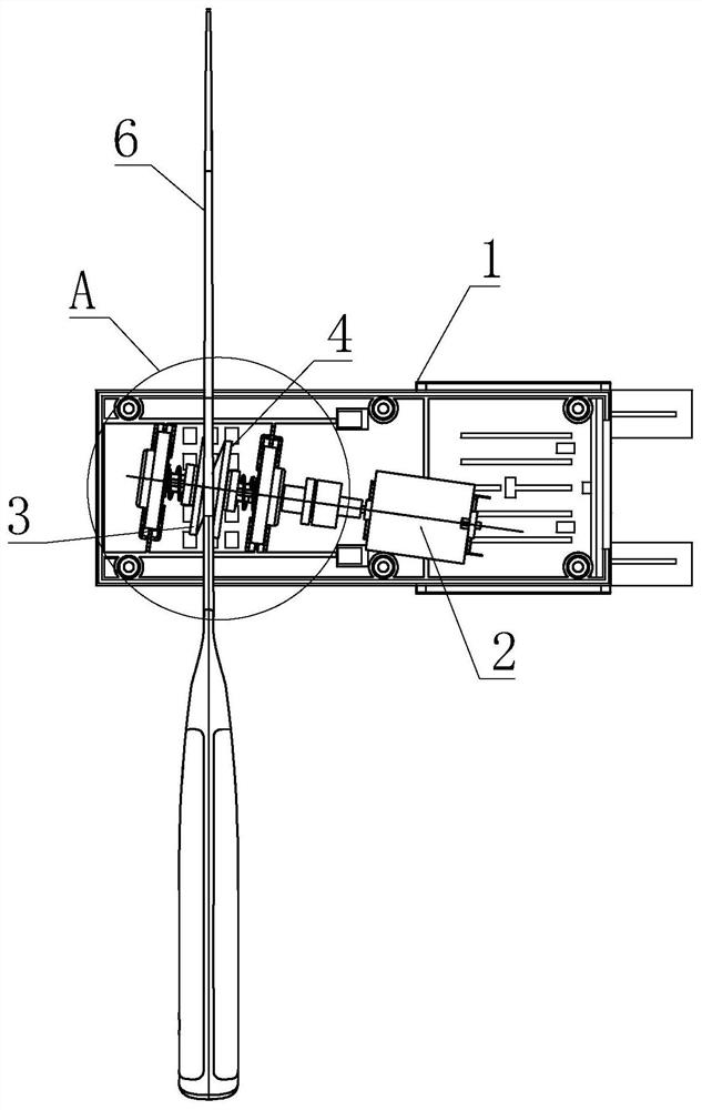
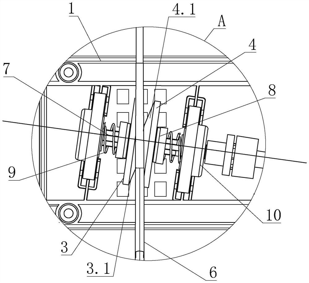
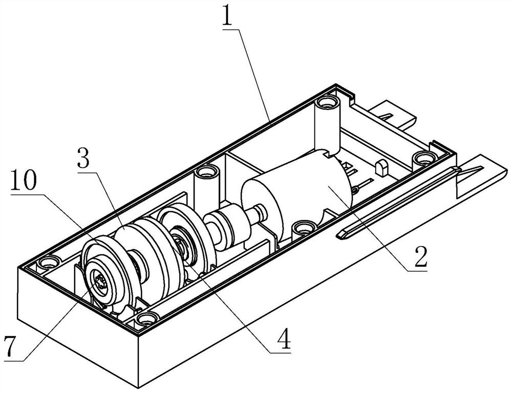
[0022] see Figure 1-6 As shown, a double-sided simultaneous sharpening device is characterized in that it includes: a casing 1, the casing 1 is provided with a sharpening mechanism, and the sharpening mechanism includes a motor 2, a first sharpener 3 and a second Two knife sharpeners 4, the motor 2 is in transmission connection with the first knife sharpener 3 and the second knife sharpener 4, and the first knife sharpener 3 and the second knife sharpener 4 are coaxially arranged through the rotating shaft 7, and The rotating shaft 7 is arranged obliquely to the tool 6 to be ground;

[0023] The first sharpener 3 includes a first sharpening surface 3.1 inclined to the rotation axis 7, the second sharpener 4 includes a second sharpening surface 4.1 inclined to the rotation axis 7, and the first sharpening surface 3.1 and The second sharpening...


PUM


Abstract

The invention discloses cutter polishing equipment capable of simultaneously polishing double sides and aims to provide cutter polishing equipment capable of simultaneously polishing double sides. The cutter polishing equipment is simple in structure and good in cutter polishing effect and comprises a machine shell, wherein the machine shell is provided with a cutter polishing mechanism; the cutter polishing mechanism comprises a motor, a first cutter polishing machine and a second cutter polishing machine; the motor is in transmission connection with the first cutter polishing machine and the second cutter polishing machine; the first cutter polishing machine and the second cutter polishing machine are coaxially arranged through a rotating shaft; the rotating shaft is inclined to a cutter to be polished; the first cutter polishing machine comprises a first cutter polishing surface which is inclined relative to the rotating shaft; the second cutter polishing machine comprises a second cutter polishing surface which is inclined relative to the rotating shaft; the first cutter polishing surface and the second cutter polishing have same inclination angles with the rotating shaft; the first cutter polishing surface and the second cutter polishing surface abut against two sides of the cutter to be polished respectively; and the abutting surface between the first cutter polishing surface and the cutter to be polished and the abutting surface between the second cutter polishing surface and the cutter to be polished are arranged in a staggered mode. The invention relates to the technical field of polishing equipment.

Description

technical field [0001] The invention relates to the technical field of grinding equipment, and more specifically relates to a double-sided simultaneous sharpening equipment. Background technique [0002] Knife sharpeners are used to sharpen various tools such as kitchen knives and scissors. It has played a good role in controlling the consistency and stability of the quality of knives. Now the knife sharpener has already replaced manual sharpening and realized automatic sharpening. Knife. Traditional knife sharpeners are generally equipped with two sharpeners, and a sharpening area for sharpening knives is formed between the two sharpeners. When the knife to be sharpened is inserted into the sharpening area, the horizontal direction of the knife to be sharpened is opposite to each other. Both sides of the knife sharpener are polished at the same time. When the gap between the sharpening area and the knife to be sharpened is large, the two sides of the knife to be sharpened ...

Claims


Application Information

Patent Timeline
IPC IPC(8): B24B3/52B24B3/36B24B27/00B24B47/12
CPCB24B3/52B24B3/36B24B27/0076B24B47/12
Inventor 李武建
Owner 余姚市诺顿电器有限公司
Learn More