
Lifter ejector pin linkage mechanism

A technology of linkage mechanism and inclined top spring, which is applied in the field of injection molds, can solve the problems of speeding up the demoulding speed and difficulty of demoulding, and achieve the effect of improving the demoulding rate, simple structure and ingenious design

Inactive Publication Date: 2021-12-28
ZHEJIANG KAIHUA MOLDS
View PDF9 Cites 0 Cited by
  • Summary
  • Abstract
  • Description
  • Claims
  • Application Information

AI Technical Summary

Problems solved by technology

[0005] The present invention is to solve the problem of difficult demoulding of products with relatively complex shapes when dealing with undercuts in the ejection process of injection molded products. The second inclined ejector rod pushes the stepped inclined ejector block to separate the bolt groove on the product from the spring pin. After the inclined ejector block is separated from the first movable template, the inclined ejector block is separated from the first movable template under the action of the guide block and the driving spring. The product is completely separated, which speeds up the demoulding speed of some products with complex shapes when dealing with undercuts, and the structure is simple and easy to install and maintain

Method used


Image

  • Lifter ejector pin linkage mechanism
  • Lifter ejector pin linkage mechanism
  • Lifter ejector pin linkage mechanism

Examples


Embodiment 1

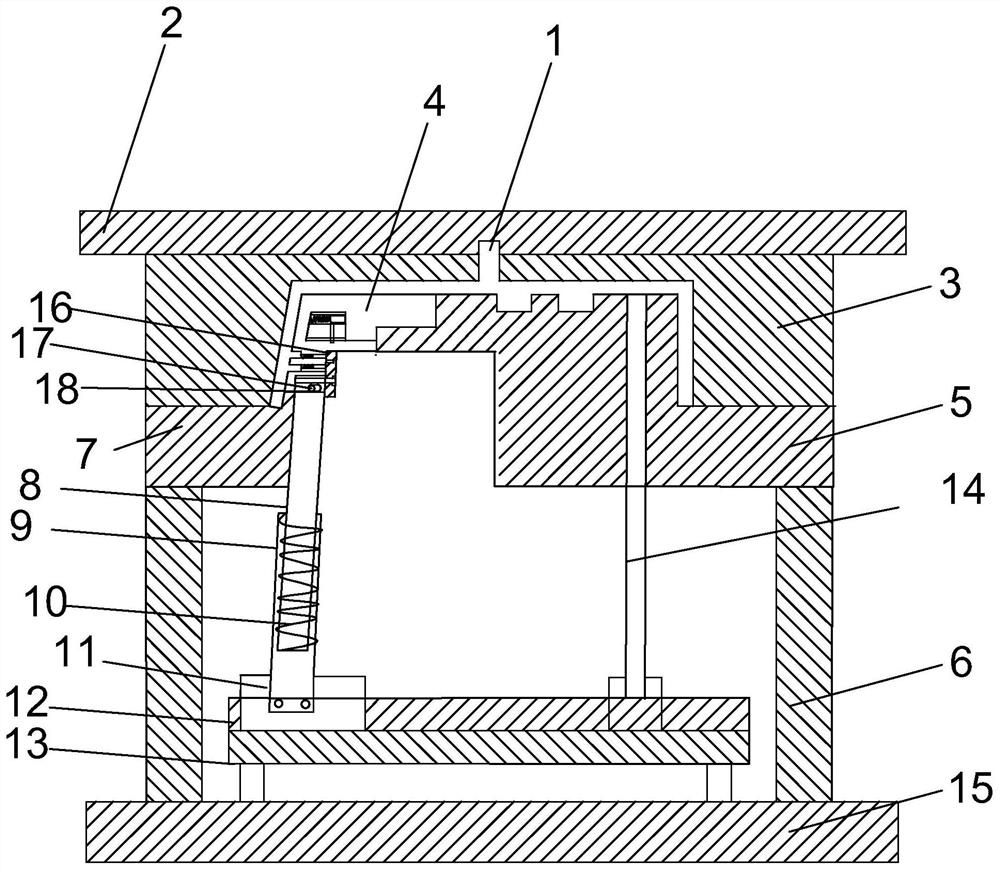
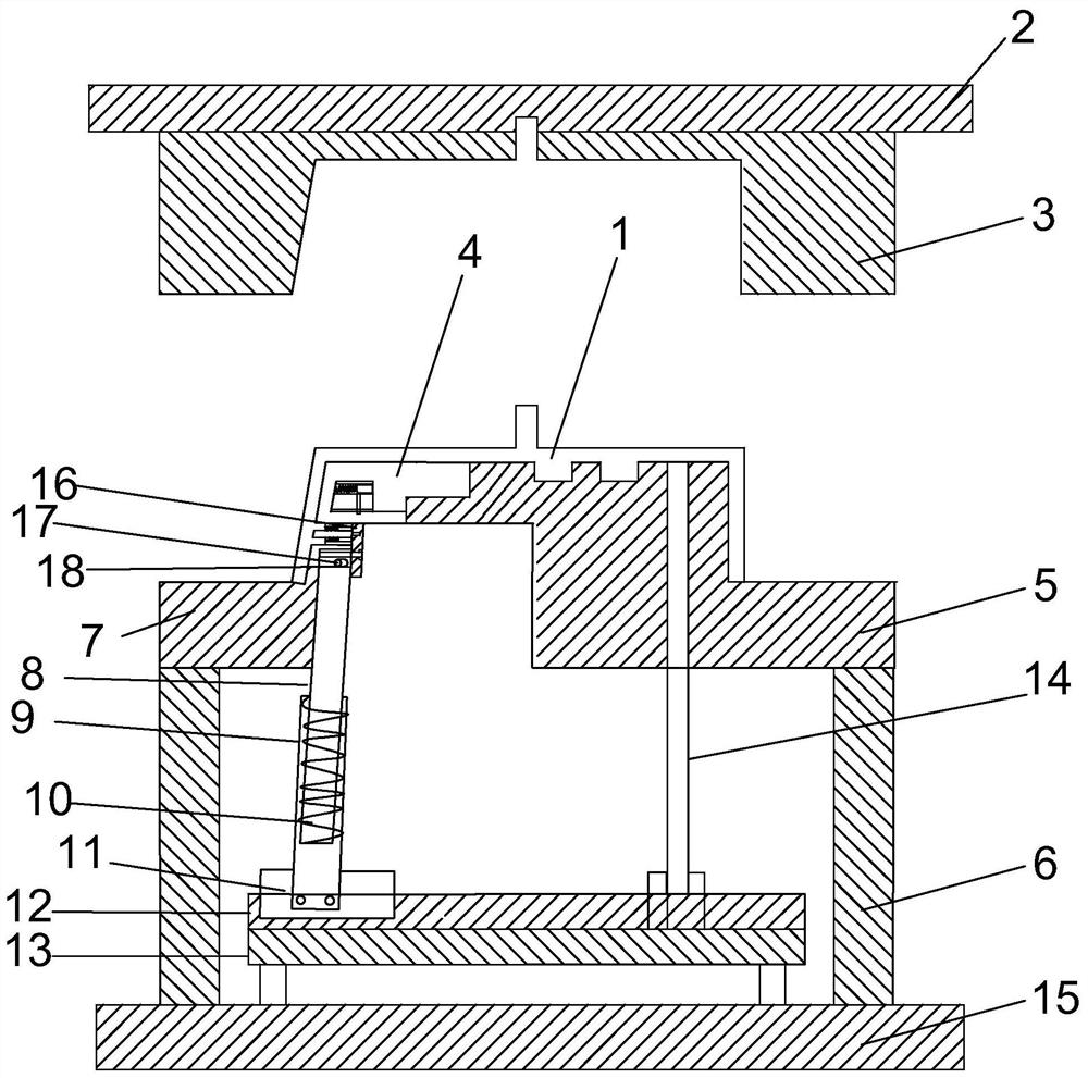
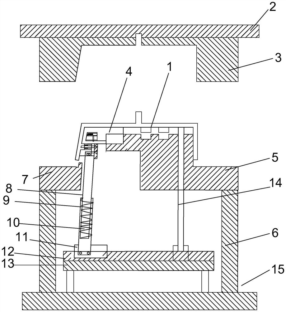
[0025] This embodiment proposes a kind of linkage mechanism of inclined ejector pin, refer to figure 1, comprising a slanted top block 4, the bottom of the slanted top block 4 is connected with a first slanted top rod 8, the top of the first slanted top rod 8 is provided with a limit nut 17, and the bottom of the slanted top block 4 is provided with a waist-shaped stop hole 18, the limit The nut 17 is slidably connected to the waist-shaped limiting hole 18, and the second inclined ejector rod 9 is provided at the lower part of the first inclined ejector rod 8. Sliding block 4 is provided with slide tube 41, and slide tube 41 is provided with drive spring 43 inside, and one end of drive spring 43 is provided with and contacts with the inner wall of slant block 4, and the other end of drive spring 43 is fixedly connected with guide block 42, guides The bottom of the block 42 is provided with a guide rod 44 , and the bottom of the guide rod 44 is slidably connected to the waist-s...


PUM


Abstract

The invention discloses a lifter ejector pin linkage mechanism. The lifter ejector pin linkage mechanism comprises a lifter block, the lower portion of the lifter block is connected with a first lifter rod, the top of the first lifter rod is provided with a limiting nut, the bottom of the lifter block is provided with a kidney-shaped limiting hole, the limiting nut is slidably connected to the kidney-shaped limiting hole, and a second lifter rod is arranged at the lower portion of the first lifter rod. The step-shaped lifter block is pushed by the first lifter rod and the second lifter rod, so that a bolt groove on a product is separated from an ejector pin, and after the lifter block is separated from a first movable mold plate, the lifter block is completely separated from the product under the action of a guide block and a driving spring, so that the demolding speed of part of products with relatively complicated shapes during undercut treatment is increased, the structure is simple, and installation and maintenance are convenient.

Description

technical field [0001] The invention relates to the technical field of injection molds, in particular to a linkage mechanism of inclined ejector pins. Background technique [0002] Injection mold is a production tool that can repeatedly produce plastic parts or products in large quantities. This kind of mold is to form one or more cavities after assembly by forming parts, or to shape the shape of the product we need. Injection molds are the most complex structures of all plastic molds. It is the most widely used mold with the highest manufacturing and processing precision. When the injection mold is working, it must be installed on the plastic injection machine. The injection machine realizes the opening and closing of the dynamic and fixed molds, and forms the required products in the following order: mold closing, injection of melt into the cavity, pressure maintenance and cooling , Open the mold, push out the product and then close the mold. The level of mold producti...

Claims


Application Information

Patent Timeline
IPC IPC(8): B29C45/33B29C45/40B29C45/44
CPCB29C45/332B29C45/4005B29C45/44
Inventor 梁正华梁凯林连明王华良
Owner ZHEJIANG KAIHUA MOLDS
Features
  • Generate Ideas
  • Intellectual Property
  • Life Sciences
  • Materials
  • Tech Scout
  • Unparalleled Data Quality
  • Higher Quality Content
  • 60% Fewer Hallucinations
Learn More