Automatic demoulding device and method for concrete test block

A concrete test block and automatic demoulding technology, applied in the direction of unloading devices, manufacturing tools, etc., can solve the problems of easy scratches, easy bump deformation, large temperature deformation, etc., to ensure convenience and automation, and ensure fastening The effect of connecting and ensuring the molding size

Active Publication Date: 2016-02-24
CHONGQING CONSTR ENG NEW BUILDING MATERIALS +1
View PDF6 Cites 0 Cited by
  • Summary
  • Abstract
  • Description
  • Claims
  • Application Information

AI Technical Summary

Problems solved by technology

The installation and demolition of concrete steel formwork is cumbersome and inefficient, and is greatly affected by the human factors of the operator, making it difficult to guarantee the accuracy of test formwork installation required by the standard JG237-2008
[0004] Plastic molds are mostly made of engineering plastics, and there are small holes in the bottom plate of the test mold. The air pressure provided by the air pump is needed to impact the test block through the small holes in the bottom plate of the test mold to make it demould, but the temperature deformation of the plastic test mold is large. , easy to bump and deform during use, short service life, scratches are easily generated on the inner surface of the test mold, and the small holes reserved on the bottom plate are prone to slurry leakage, which cannot guarantee the dimensional accuracy and surface roughness of the test mold required by the standard JG237-2008
[0005] In addition, the automation degree of the existing demoulding device is not high, the demoulding effect is poor and the efficiency is low

Method used


Image

  • Automatic demoulding device and method for concrete test block
  • Automatic demoulding device and method for concrete test block

Examples


Embodiment Construction

[0015] Below in conjunction with accompanying drawing and specific embodiment the present invention will be described in further detail:

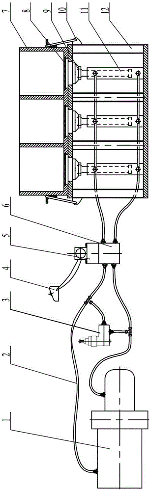
[0016] Such as figure 1 with figure 2 Shown: the embodiment of the present invention provides a kind of automatically controlled demoulding device and demoulding method for concrete test block, including metal triple mold 7 provided with lugs, demoulding support 12 for vertically fixing triple mold 7, jacking The three hydraulic cylinders 11 of the triple mold 7 and the hydraulic power unit 1, each center of the bottom plate of the triple mold 7 is provided with a test mold pallet 8, and the upper end of the hydraulic cylinder 11 is hinged with a top that is placed at the center of the lower surface of the mold trial pallet 8. Block 9, the bottom of the hydraulic cylinder 11 is welded and fixed with the demoulding bracket 12, the inlet and outlet of the hydraulic power unit 1 are respectively connected to the electromagnetic reversing val...


PUM

PropertyMeasurementUnit
thicknessaaaaaaaaaa

Abstract

The invention relates to a demoulding device and a demoulding method, in particular to a concrete briquette automatic demoulding device and a demoulding method. The device comprises a forming test mould, a demoulding support base, three hydraulic oil cylinders and a hydraulic power device, wherein the forming test mould is a three-connection mould, test mould support boards are arranged in the centers of the baseboards of the forming test mould, sealing rings are arranged around the test mould support boards, a positioning groove is formed in the upper surface of the demoulding support base, the side wall of the groove is provided with a hinged buckle which tightly clamps the three-connection mould, a basket-like nut is arranged in the middle part of the hinged buckle, the three hydraulic oil cylinders are arranged in parallel, top blocks are hinged to the upper ends of the hydraulic oil cylinders, the lower ends of the hydraulic oil cylinders are fixed with a demoulding support, an electromagnetic reversing valve pinboard and a direct-acting overflow valve are respectively connected onto the oil inlet and the oil outlet of the hydraulic power unit, the electromagnetic reversing valve pinboard is connected with the three hydraulic oil cylinders in parallel, an electromagnetic reversing valve is installed on the electromagnetic reversing valve pinboard, and the electromagnetic reversing valve and the hydraulic power unit are electrically connected with an electrically controlled box. The concrete briquette automatic demoulding device is simple in mould and high in forming precision, the automatic demoulding does not be damaged easily.

Description

technical field [0001] The invention relates to a demoulding device and method, in particular to an automatic demoulding device and method for a concrete test block. Background technique [0002] In order to test the performance of concrete, it is often necessary to make standard test blocks with concrete test molds. At present, there are two types of concrete test molds: steel molds and plastic molds. [0003] Concrete steel molds are mostly combined, consisting of bottom formwork, side formwork, partitions, bracket swing bolts and wing nuts. Before the test block is formed, it is necessary to assemble the concrete test form. When assembling, first place the two side templates relatively vertically on the plane of the bottom template, insert the shafts on the swing bolts into the grooves at both ends of the side templates, fix them slightly, and then insert the partitions into the grooves of the side templates. Align the two side templates to ensure that the mold cavity ...

Claims


Application Information

Patent Timeline
Patent Type & Authority Patents(China)
IPC IPC(8): B28B13/06
CPCB28B13/065
Inventor 陈敬杨再富张兴礼李斯祺石从黎金超樊先平
Owner CHONGQING CONSTR ENG NEW BUILDING MATERIALS
Why Eureka
Try Eureka