
Demolding device for composite material and demolding method

A composite material and demolding device technology, applied in the field of composite material processing, can solve problems such as inability to detach, inconvenient demolding process, inability to synchronously drive demoulding, etc., achieve high energy saving, avoid continuous bonding, and improve demoulding. effect of speed

Inactive Publication Date: 2021-10-22
GUANGLIAN AVIATION IND CO LTD
View PDF6 Cites 0 Cited by
  • Summary
  • Abstract
  • Description
  • Claims
  • Application Information

AI Technical Summary

Problems solved by technology

[0005] The purpose of the present invention is to provide a demoulding device and a demoulding method for composite materials, so as to solve the problem that the demoulding mechanism cannot be synchronously driven to assist the demoulding of composite materials when the upper and lower molds are separated in the market, and it is not convenient. The problem that the product attached to the upper mold is quickly detached requires the use of additional auxiliary tools for demoulding, and the demoulding process is inconvenient.

Method used


Image

  • Demolding device for composite material and demolding method
  • Demolding device for composite material and demolding method
  • Demolding device for composite material and demolding method

Examples


Embodiment Construction

[0028] The following will clearly and completely describe the technical solutions in the embodiments of the present invention with reference to the accompanying drawings in the embodiments of the present invention. Obviously, the described embodiments are only some, not all, embodiments of the present invention. Based on the embodiments of the present invention, all other embodiments obtained by persons of ordinary skill in the art without making creative efforts belong to the protection scope of the present invention.

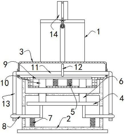
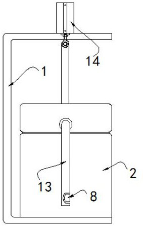
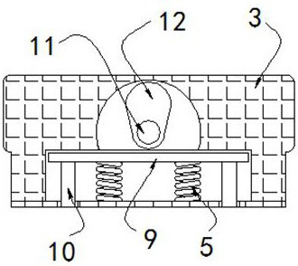
[0029] see Figure 1-5 , the present invention provides a technical solution: a demoulding device for composite materials, comprising:

[0030] The mounting frame 1 has a lower mold 2 installed on the bottom side, and an upper mold 3 is arranged on the upper side of the lower mold 2;

[0031] The hydraulic cylinder 14 is installed on the upper side of the mounting frame 1 whose side view is a "C"-shaped structure, and the lower end of the hydraulic cylinder 1...


PUM


Abstract

The invention discloses a demolding device for a composite material and a demolding method. The demolding device comprises a mounting rack, a hydraulic cylinder, a lower mounting plate and supporting frames; the bottom side of the mounting rack is provided with a lower mold, and the upper side of the lower mold is provided with an upper mold; the hydraulic cylinder is mounted at the upper side of the mounting rack of which the side view surface is of a C-shaped structure, and the lower end of the hydraulic cylinder is connected with the upper mold; the lower mounting plate is positioned in the lower part of the lower mold, and lower ejector rods are symmetrically mounted at the upper side of the lower mounting plate; the supporting frames are symmetrically mounted at the lower side of the lower mounting plate, and the lower sides of the supporting frames are elastically connected with the lower mold through extension springs. According to the demolding device for the composite material, a connecting rod is rotated, the connecting rod and a supporting rod are controlled to be clamped, and during demolding, the supporting rod can be synchronously pulled to move through the connecting rod, so that a demolding mechanism composed of the lower mounting plate and the lower ejector rods is controlled to eject a product, and the product is assisted to be separated from the lower mold; and the whole structure can be driven only by linking a separating mechanism of the upper mold and the lower mold, other driving equipment is not needed, and the energy-saving performance is high.

Description

technical field [0001] The invention relates to the technical field of composite material processing, in particular to a demoulding device and a demoulding method for composite materials. Background technique [0002] Composite materials are human-shaped materials designed and manufactured according to people's needs. They maintain the performance advantages of each component material and are more suitable for practical use. When preparing molded products from composite materials, molds are required for rapid production. [0003] However, the existing molds for the preparation of composite materials still have deficiencies in the process of use. When the upper and lower molds are separated, the demoulding mechanism cannot be synchronously driven to assist the demoulding of the composite material, and it is not easy to remove the mold attached to the upper mold. The product at the place is quickly detached, and additional auxiliary tools are required for demoulding, and the d...

Claims


Application Information

Patent Timeline
Patent Type & Authority Applications(China)
IPC IPC(8): B29C33/50B29C33/44B22D29/06
CPCB29C33/50B29C33/44B22D29/06
Inventor 杜晋国孙兆君陈晓君韩馥姜海洋
Owner GUANGLIAN AVIATION IND CO LTD
Features
  • Generate Ideas
  • Intellectual Property
  • Life Sciences
  • Materials
  • Tech Scout
  • Unparalleled Data Quality
  • Higher Quality Content
  • 60% Fewer Hallucinations
Learn More