
Convenient-to-demould injection mould for pipe cap

A technology for injection molds and conduits, which is applied in the field of injection molds for conduit domes, can solve the problems of separation, deformation of conduits 12, and quality degradation of conduit domes 10, etc., so as to improve molding quality, prevent deformation, and increase demoulding rate Effect

Pending Publication Date: 2020-02-18
金裕泰(惠州)实业有限公司
View PDF0 Cites 0 Cited by
  • Summary
  • Abstract
  • Description
  • Claims
  • Application Information

AI Technical Summary

Problems solved by technology

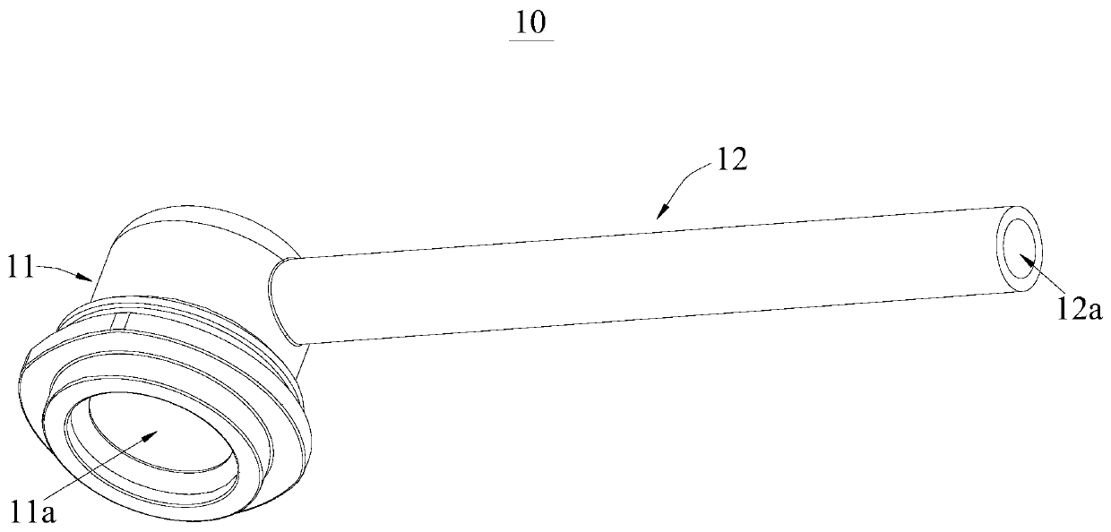
[0004] However, in the conventional injection molding method, since the bottom of the outer wall of the cover body 11 is in the shape of opening outwards, the grooves on the fixed mold for forming the outer surface of the cover body 11 need to be deep, so, Only then can the outer surface of the cover body 11 be molded, but if the groove on the fixed mold is set too deep, it is easy to cause the fixed mold to separate from the movable mold, and the injection-molded conduit dome 10 will stay in the groove of the fixed mold In this way, it is difficult to demould the duct dome 10, which increases the production difficulty of the duct dome 10; further, because the duct 12 is too long, when the sideslip structure withdraws from the duct 12, the duct 12 is prone to deformation, which in turn leads to Formed conduit dome 10 quality decline

Method used


Image

  • Convenient-to-demould injection mould for pipe cap
  • Convenient-to-demould injection mould for pipe cap
  • Convenient-to-demould injection mould for pipe cap

Examples


Embodiment Construction

[0034] In order to facilitate the understanding of the present invention, the present invention will be described more fully below with reference to the associated drawings. Preferred embodiments of the invention are shown in the accompanying drawings. However, the present invention can be embodied in many different forms and is not limited to the embodiments described herein. On the contrary, the purpose of providing these embodiments is to make the disclosure of the present invention more thorough and comprehensive.

[0035] It should be noted that when an element is referred to as being “fixed” to another element, it can be directly on the other element or there can also be an intervening element. When an element is referred to as being "connected to" another element, it can be directly connected to the other element or intervening elements may also be present. The terms "vertical," "horizontal," "left," "right," and similar expressions are used herein for purposes of ill...


PUM


Abstract

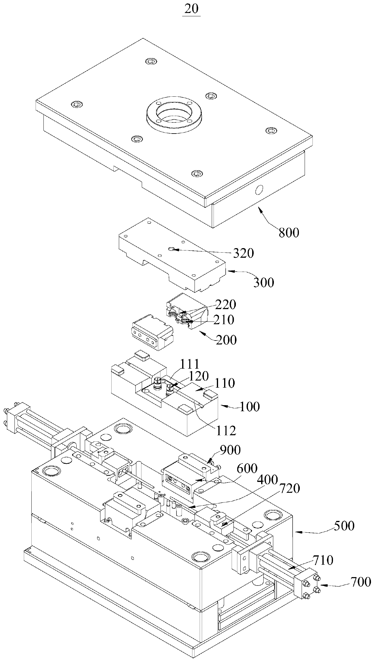
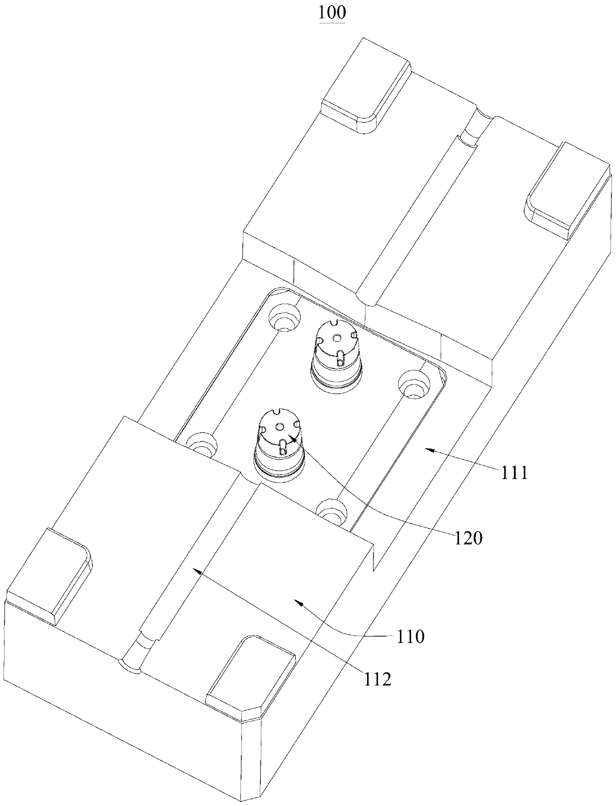
The invention provides a convenient-to-demould injection mould for a pipe cap. The injection mould comprises a moving mold assembly, a sliding mold core, a mold core of a fixed mold and a sliding rod,wherein the moving mold assembly comprises a fixed mold core and a molding boss, and the molding boss is arranged on the fixed mold core; the sliding mold core slides on the fixed mold core; a molding cavity is formed between the sliding mold core and the molding boss when the sliding mold core slides towards the molding boss, and the molding cavity is used for molding a cap body of a pipe cap; when the sliding mold core slides away from the molding boss, the cap body is separated from the sliding mold core and stays on the molding boss, the cap body is convenient to demould, and the demoulding rate of the pipe cap is increased; and when the mold core of the fixed mold is buckled on the fixed mold core, a pipeline cavity is formed between the mold core of the fixed mold and the fixed moldcore, the pipeline cavity is used for molding a pipe of the pipe cap, and the sliding rod is accommodated in the pipeline cavity and is in butt joint with the molding boss. During demolding, the pipestays on the fixed mold core, so that the deformation of the pipe is prevented, and the molding quality of the pipe cap is effectively improved.

Description

technical field [0001] The invention relates to the technical field of injection molds, in particular to an injection mold for a catheter dome cap that is easy to demould. Background technique [0002] The injection mold is used to form plastic products. The screw of the injection molding machine extrudes the molten plastic into the cavity of the injection mold, thereby forming the plastic product in the cavity. [0003] see figure 1 , is a conduit dome 10 for a water pump, the conduit dome 10 includes a cover 11 and a conduit 12, the conduit 12 is arranged on the cover 11, a bottom groove 11a is provided on the cover 11, and a bottom groove 11a is provided on the conduit 12 The circular hole 12a communicates with the bottom groove 11a. For the catheter round cover 10, the conventional injection molding method is to fasten the movable mold and the fixed mold together, set a boss on the movable mold, let the boss form the bottom groove 11a of the cover body 11, and the fixe...

Claims


Application Information

Patent Timeline
Patent Type & Authority Applications(China)
IPC IPC(8): B29C45/44
CPCB29C45/44
Inventor 陆洪彬何平周陆洪祥
Owner 金裕泰(惠州)实业有限公司
Features
  • Generate Ideas
  • Intellectual Property
  • Life Sciences
  • Materials
  • Tech Scout
  • Unparalleled Data Quality
  • Higher Quality Content
  • 60% Fewer Hallucinations
Learn More