Blow-molded table tennis ball edge removing equipment
A table tennis and equipment technology, applied in the field of blow molding table tennis edge removal equipment, can solve laborious and troublesome problems
- Summary
- Abstract
- Description
- Claims
- Application Information
AI Technical Summary
Problems solved by technology
Method used
Image

Examples
Embodiment 1
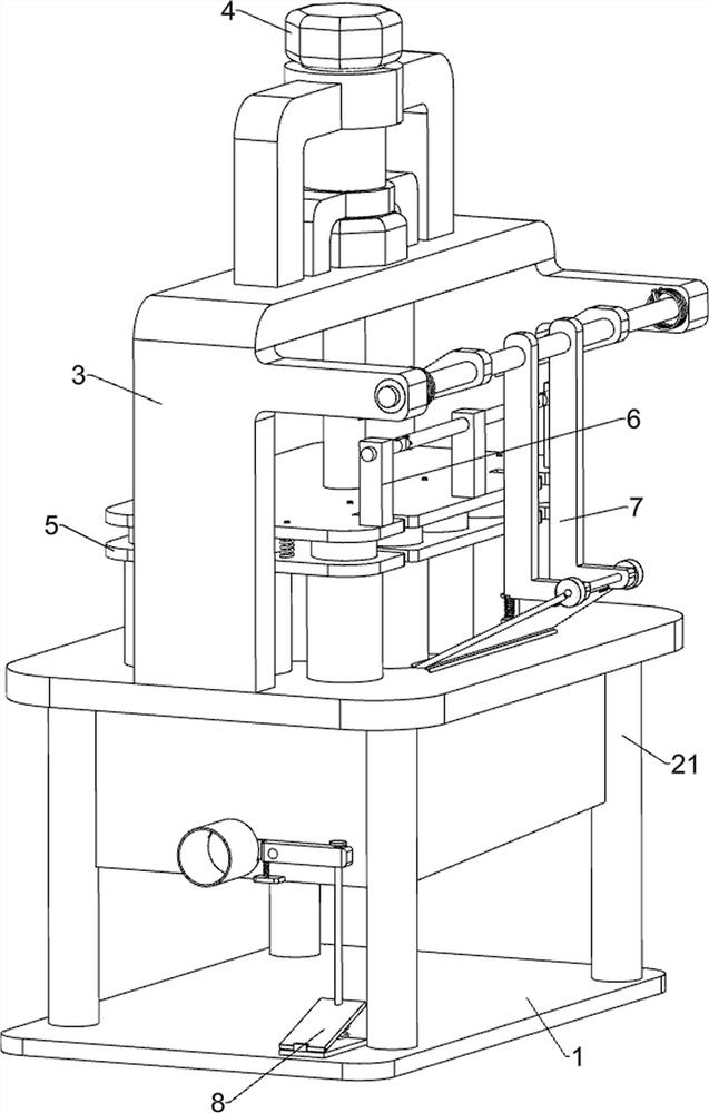
[0027] A kind of blow molding table tennis edge removal equipment, such as Figure 1-Figure 4 As shown, it includes a bottom plate 1, a support column 21, a ball storage box 22, a porous placement table 23, a ball outlet pipe 24, a support table 3, a demoulding mechanism 4, and a crimping mechanism 5, and the top of the bottom plate 1 is fixedly connected with Four support columns 21, four support columns 21 tops are fixedly connected with porous placement platform 23, the bottom of porous placement platform 23 is fixedly connected with ball storage box 22, and the top of porous placement platform 23 is fixedly connected with support platform 3, support platform 3 The top is provided with demoulding mechanism 4, and demoulding mechanism 4 is provided with crimping mechanism 5, and crimping mechanism 5 cooperates with porous placement platform 23, and ball storage box 22 front side lower middle is fixedly connected with ball outlet pipe 24 and communicates.
[0028] The demould...
Embodiment 2
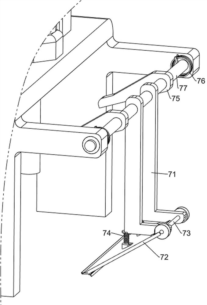
[0034] On the basis of Example 1, such as figure 1 , image 3 , Figure 5 and Figure 6 As shown, it also includes a buckle mechanism 6, and the buckle mechanism 6 includes a fixed support plate 61, a first connecting rod 62, a movable buckle 63, a second connecting rod 64 and an edge removal mechanism 7, and the top right side of the first connecting plate 44 The sides are fixedly connected with fixed support plates 61 evenly spaced, and the upper part of the middle fixed support plate 61 is fixedly connected with a second connecting rod 64. Both ends of the second connecting rod 64 are connected with movable buckles 63 in a rotating manner, and the front and rear sides are fixedly supported. Plate 61 tops are fixedly pierced with the first connecting rod 62, the inner end of the first connecting rod 62 contacts and cooperates with the movable buckle 63, and the edge removing mechanism 7 is arranged between the two ends on the right side of the supporting platform 3, and th...
Embodiment 3
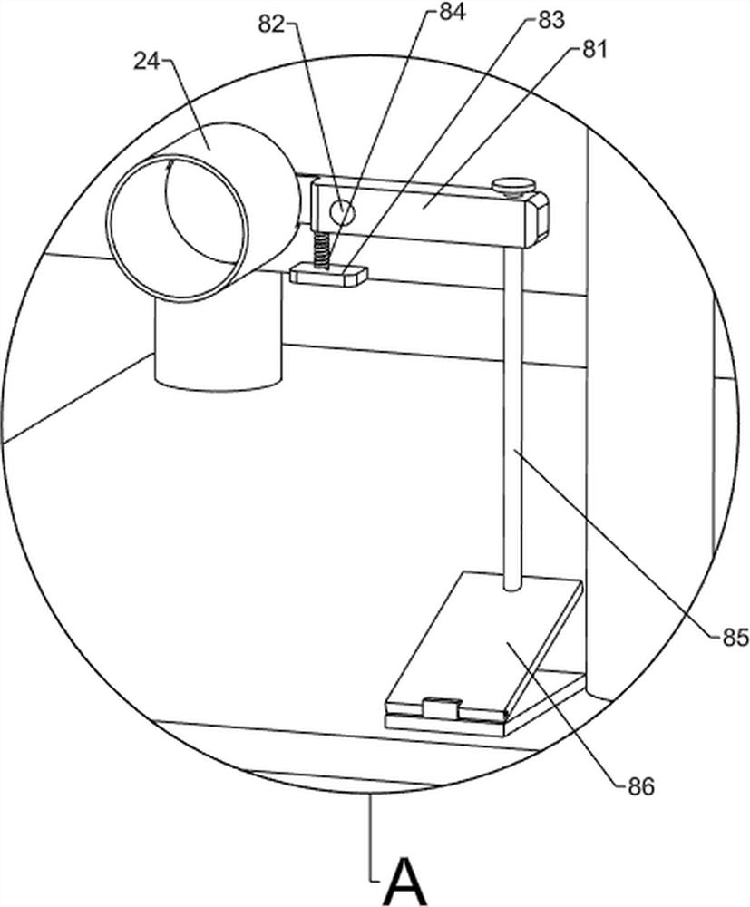
[0039] On the basis of embodiment 1 and embodiment 2, such as figure 1 , figure 2 and Figure 7 Shown, also comprise ball-out mechanism 8, ball-out mechanism 8 includes ball baffle plate 81, cylinder 82, support plate 83, the 3rd compression spring 84, rope 85 and pedal 86, ball storage box 22 outer front side bottom right sides The side is fixedly connected with a cylinder 82, and the rotation type on the cylinder 82 is connected with a ball blocking plate 81, and the left end of the ball blocking plate 81 runs through the rear side of the ball pipe 24 to cooperate with it, and the lower right side of the outer front side of the ball storage box 22 is fixedly connected with a support plate 83, a third pressure spring 84 is connected between the top of the support plate 83 and the left side of the bottom of the ball baffle 81, the right part of the ball baffle 81 is fixedly pierced with a rope 85, and the top right side of the bottom plate 1 is connected with a pedal in a ro...
PUM
 Abstract
Description
Claims
Application Information
 - R&D
- Intellectual Property
- Life Sciences
- Materials
- Tech Scout
- Unparalleled Data Quality
- Higher Quality Content
- 60% Fewer Hallucinations
Browse by: Latest US Patents, China's latest patents, Technical Efficacy Thesaurus, Application Domain, Technology Topic, Popular Technical Reports.
© 2025 PatSnap. All rights reserved.Legal|Privacy policy|Modern Slavery Act Transparency Statement|Sitemap|About US| Contact US: help@patsnap.com