Timepiece

A technology of clocks and crowns, applied in the field of clocks, can solve cumbersome problems

Pending Publication Date: 2021-12-28
CITIZEN WATCH CO LTD
View PDF10 Cites 0 Cited by
  • Summary
  • Abstract
  • Description
  • Claims
  • Application Information

AI Technical Summary

Problems solved by technology

However, whenever the user wants to wind up the mainspring, he needs to first unlock the crown and then turn the crown, which sometimes feels cumbersome.

Method used


Image

  • Timepiece
  • Timepiece
  • Timepiece

Examples


no. 1 Embodiment approach

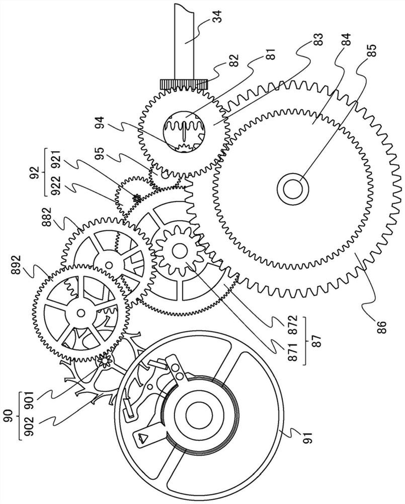
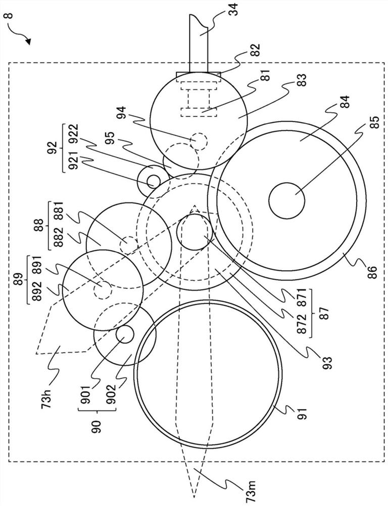
[0031] figure 1 It is a front view of the movement 8 of the watch of the embodiment, figure 2 It is a schematic diagram for explaining the outline of the movement 8 . figure 2 The relationship between the various constituent elements of the movement 8 is schematically shown in . Furthermore, figure 2 The illustration of the teeth of the gears in each constituent element is omitted.

[0032] First, refer to figure 1 and figure 2 , the operation in the state where the crown is not pulled out (hereinafter referred to as "the first state") will be described.

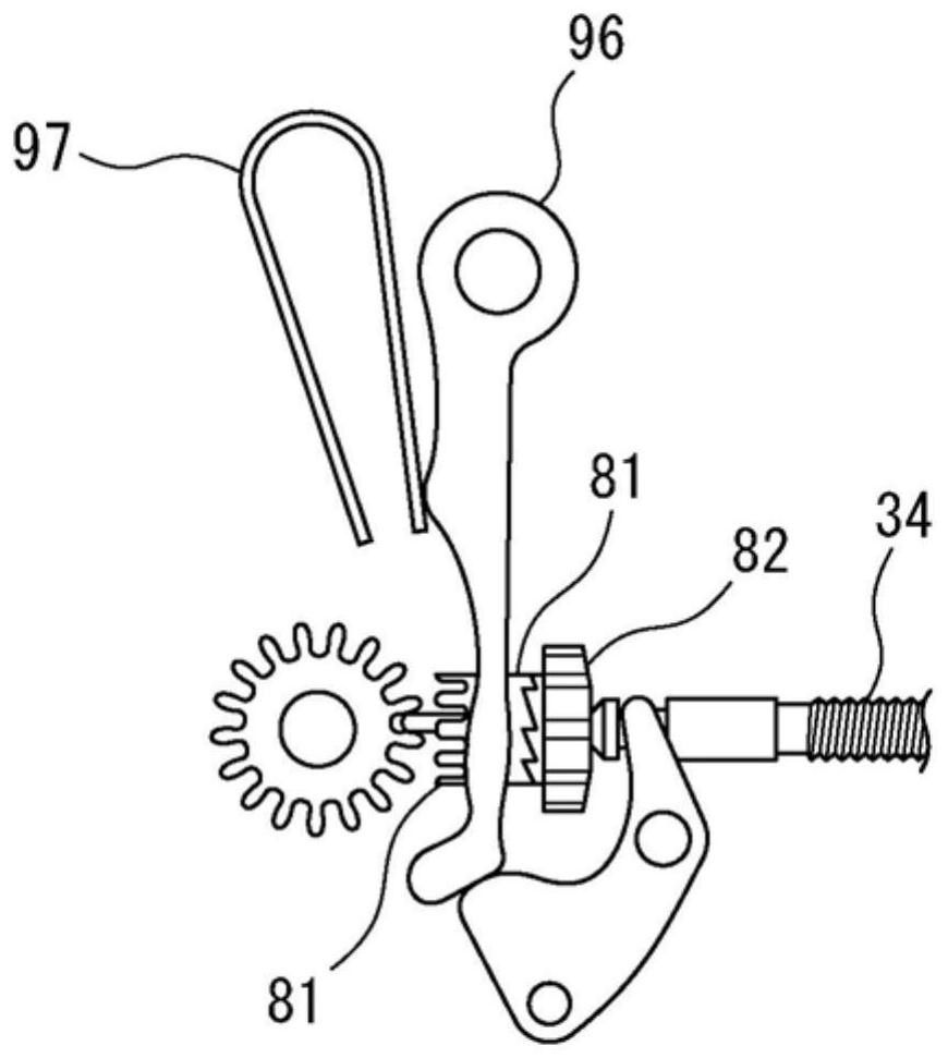
[0033] The stem 34 is a shaft-shaped member screwed to the crown, and rotates in the circumferential direction in conjunction with the rotation of the crown. On the stem 34 , a clutch wheel 81 is fitted so as to be slidable in the axial direction of the stem 34 , and a vertical wheel 82 is fitted so as to be rotatable in the circumferential direction of the stem 34 . In the first state, when the stem 34 rotates in...

no. 2 Embodiment approach

[0053] The timepiece of the second embodiment is different from the timepiece 1 of the first embodiment in the configuration of the operation portion 32 and the engagement portion 33 of the crown 3 . Next, use Figure 10 , the crown 3a of the timepiece of the second embodiment will be described.

[0054] Figure 10 It is a sectional view of the vicinity of the crown 3a of the timepiece of the second embodiment. The crown 3 a of the second embodiment includes a shaft portion 31 , an operation portion 35 , and an engagement portion 36 . Furthermore, Figure 10 The section shown is along the Figure 7-Figure 9 same line as shown in section, but Figure 10 omitted in Figure 7-Figure 9 There are illustrations of the housing 20 , the stem 34 , the back cover holder 62 , and the second bushing 72 as shown. In addition, the same code|symbol is attached|subjected to the same structure as 1st Embodiment, and description is abbreviate|omitted as appropriate.

[0055] The operati...


PUM


Abstract

A timepiece according to an embodiment makes it possible to rotate a crown even when the crown is locked using a non-design-restricting structure and comprises: an outer case having a built-in movement and a crown hole in a portion of the outer case that penetrates from the inside to the outside; a crown for operating the movement; and an engaged member connected to the outer case. The crown comprises: a shaft part that is inserted into the crown hole and connected to the movement; an operation part that holds the shaft part such that movement along the axial direction of the shaft part is possible and makes it possible to rotate the shaft part in the circumferential direction; and an engagement part that is disposed between the engaged member and the operation part, restricts the movement of the operation part in the axial direction when engaged with the engaged member, and rotatably holds the operation part whether or not engaged with the engaged member.

Description

technical field [0001] The present invention relates to timepieces. Background technique [0002] In the past, there were clocks with crowns. In such timepieces, the crown is connected to the movement via the stem. Then, the clockwork is driven by transmitting the rotational force generated by the rotation of the watch to the movement to wind up the mainspring of the movement. In addition, in such a timepiece, the crown can be pulled out, and the user of the timepiece can rotate the crown in the pulled-out state to perform time adjustment operations and the like. [0003] In such timepieces, in order to prevent unintended operations by the user, some of the timepieces lock the crown on the case through a screw structure or the like to restrict the pulling out of the crown. However, whenever the user wants to wind up the mainspring, he needs to first unlock the crown and then rotate the crown, which sometimes feels cumbersome. Patent Document 1 describes a timepiece whose...

Claims


Application Information

Patent Timeline
Patent Type & Authority Applications(China)
IPC IPC(8): G04B37/10
CPCG04B37/103G04B3/041
Inventor 箭原祐二
Owner CITIZEN WATCH CO LTD
Why Eureka
Try Eureka