Lighting device for surgical operation

A technology for lighting devices and surgical operations, which is applied in the direction of lighting devices, lighting auxiliary devices, portable lighting devices, etc., can solve the problems of lighting devices without self-cleaning ability, affecting lighting conditions, and the lamp surface is easily polluted by dust, so as to ensure the prevention of Dust storage, guarantee the effect of use, increase the effect of service life

Inactive Publication Date: 2021-12-31
郑月英
View PDF0 Cites 0 Cited by
  • Summary
  • Abstract
  • Description
  • Claims
  • Application Information

AI Technical Summary

Problems solved by technology

[0003] The existing surgical lighting device only has lighting function. In the long-term exposure to the external environment, because the lighting device has no self-cleaning ability, the lamp surface is easily polluted by dust and affects the lighting situation. In view of this, we propose a surgical Surgical lighting devices are used to solve the above problems

Method used


Image

  • Lighting device for surgical operation
  • Lighting device for surgical operation
  • Lighting device for surgical operation

Examples


Embodiment 1

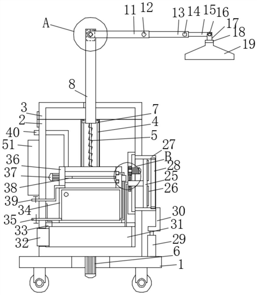
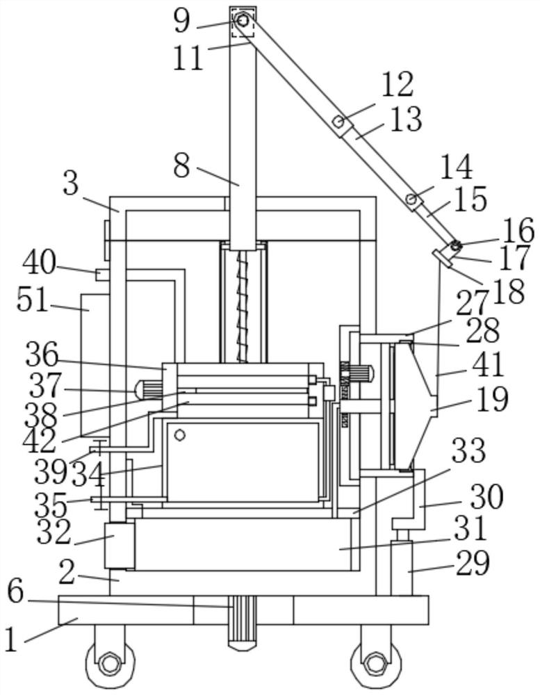
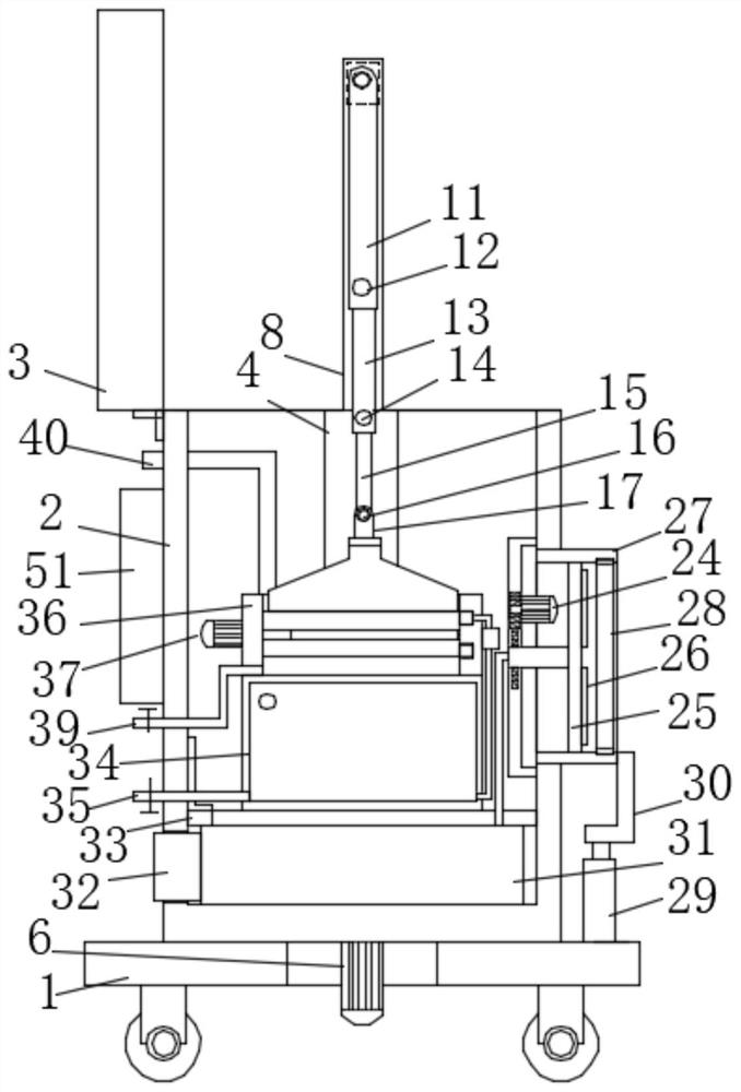
[0025] see Figure 1-10 , a surgical lighting device, comprising a mobile base 1, a bottom box 2 is fixedly installed on the mobile base 1, and a box cover 3 is hinged on the bottom box 2, and tubes are fixedly installed on the front and rear sides of the bottom box 2, respectively. Cover 4, and the two tube covers 4 are respectively penetrated with threaded rods 5, and the two threaded rods 5 are all rotatably installed on the bottom box wall at the inner end of the bottom box 2, and the two threaded rods 5 are respectively threaded with sleeve rods 8, An installation cavity is provided on the bottom wall of the bottom box 2, and two threaded rods 5 extend into the installation cavity, and the extension ends of the two threaded rods 5 are respectively fixedly sleeved with engaging teeth 43, and the two engaging teeth 43 are sleeved There is the same transmission chain 44, and the first motor 6 is fixedly installed on the outer box wall at the bottom end of the bottom box 2, a...

Embodiment 2

[0036] see Figure 1-10 , a surgical lighting device, comprising a mobile base 1, a bottom box 2 is fixedly installed on the mobile base 1, and a box cover 3 is hinged on the bottom box 2, and tubes are fixedly installed on the front and rear sides of the bottom box 2, respectively. Cover 4, and the two tube covers 4 are respectively penetrated with threaded rods 5, and the two threaded rods 5 are all rotatably installed on the bottom box wall at the inner end of the bottom box 2, and the two threaded rods 5 are respectively threaded with sleeve rods 8, An installation cavity is provided on the bottom wall of the bottom box 2, and two threaded rods 5 extend into the installation cavity, and the extension ends of the two threaded rods 5 are respectively fixedly sleeved with engaging teeth 43, and the two engaging teeth 43 are sleeved There is the same transmission chain 44, and the first motor 6 is fixedly installed on the outer box wall at the bottom end of the bottom box 2, a...


PUM


Abstract

The invention discloses a lighting device for surgical operation, which comprises a movable base and is characterized in that a bottom box is fixedly installed on the movable base, a box cover is hinged to the bottom box, barrel covers are fixedly installed on the two inner box walls of the front side and the rear side of the bottom box respectively, and threaded rods penetrate through the two barrel covers respectively; the two threaded rods are both rotationally mounted on the bottom box wall of the inner end of the bottom box, the two threaded rods are each sleeved with a sleeve rod in a threaded mode, the same rotating rod is rotationally mounted on the adjacent sides of the top side ends of the two sleeve rods, and a telescopic rod assembly is fixedly mounted on the rotating rod; and the shaft assembly comprises a fixed shaft part, an inserting part and a rotating shaft part, the fixed shaft part is hinged to the rotating shaft part, the inserting part is fixedly installed at the side end, close to the fixed shaft part, of the rotating shaft part, and an inserting groove corresponding to the inserting part is formed in the fixed shaft part.

Description

technical field [0001] The invention relates to the technical field of medical equipment, in particular to a surgical lighting device. Background technique [0002] In 809, the British chemist David invented the arc lamp, and mankind entered the era of using electric lighting. In 1906, Edison invented the household light bulb with tungsten wire as the filament. In the future, incandescent lamps, fluorescent lamps, energy-saving lamps, neon lamps, and various high-tech lamps invented by modern high-tech have sprung up on the stage of lighting. It greatly facilitates people's production and life. With the development of medical technology, Auxiliary lighting devices designed for surgical operations have also emerged as the times require. [0003] The existing surgical lighting device only has lighting function. In the long-term exposure to the external environment, because the lighting device has no self-cleaning ability, the lamp surface is easily polluted by dust and affec...

Claims


Application Information

Patent Timeline
IPC IPC(8): F21L2/00F21V21/06F21V21/36F21V21/14F21V21/22B08B5/04B08B3/04F21V21/26F21W131/205
CPCF21L2/00F21V21/06F21V21/36F21V21/14F21V21/22B08B5/04B08B3/04F21V21/26F21W2131/205
Inventor 郑月英樊欢
Owner 郑月英
Why Eureka
Try Eureka