
Grouting pipe construction method for post grouting of cast-in-place pile

A construction method and grouting pipe technology, which are applied in sheet pile walls, infrastructure engineering, construction, etc., can solve the problems of high grouting pressure, failure to open grouting holes, and failure to reach grouting volume, etc. Large grouting space and the effect of improving construction quality

Active Publication Date: 2022-01-04
CHINA RAILWAY GUANGZHOU ENG GRP CO LTD +1
View PDF2 Cites 0 Cited by
  • Summary
  • Abstract
  • Description
  • Claims
  • Application Information

AI Technical Summary

Problems solved by technology

[0004] In view of the current related technologies, the inventors found that during the process of pouring concrete into the pile foundation, the grout holes at the bottom of the pile bottom grouting pipe and the grouting holes of the pile side grouting pipe are easily completely covered by the pile body concrete. If the plug is not timely, the subsequent grouting pressure will be too high, and even the grouting hole will not be opened, so that the designed grouting volume will not be reached, which will directly affect the improvement of the bearing capacity of the pile foundation, which needs to be improved

Method used


Image

  • Grouting pipe construction method for post grouting of cast-in-place pile
  • Grouting pipe construction method for post grouting of cast-in-place pile
  • Grouting pipe construction method for post grouting of cast-in-place pile

Examples


Embodiment Construction

[0034] The application will be described in further detail below in conjunction with the accompanying drawings.

[0035] The embodiment of the present application discloses a grouting pipe construction method for grouting after pouring piles, such as figure 1 with figure 2 shown, including the following steps:

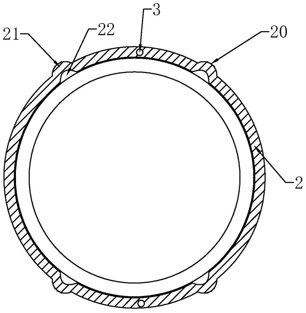
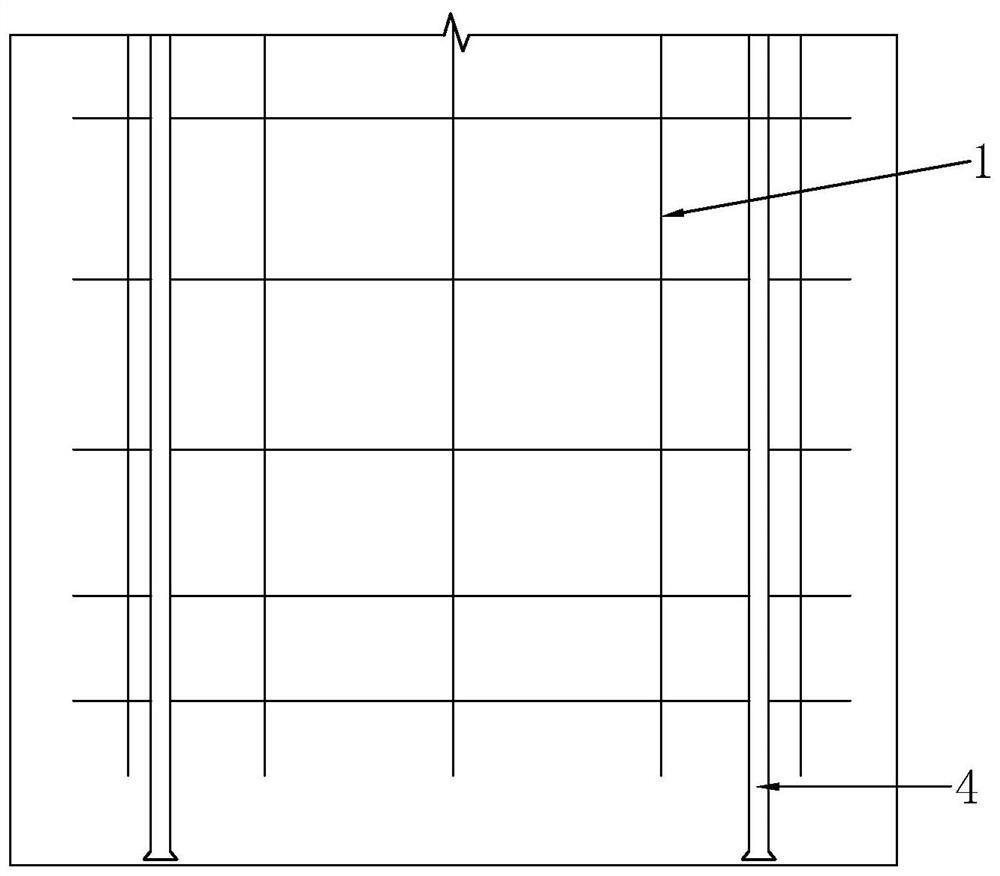
[0036] Step 1: making the pile side grouting hose 2, and selecting a number of predetermined positions on the completed pile side grouting hose 2 body, and then opening a number of side grouting holes 20 at the predetermined positions;

[0037] Step 2: install several pile side grouting hoses 2 around the outer circumference of the reinforcement cage 1 on the pile side. The side of the grout hose 2 with the side grout hole 20 should protrude away from the reinforcement cage 1, so that the outer side of the pile side grouting hose 2 forms an outer convex part 21, and the inner side forms an inner concave part 22;

[0038] Step 3: install a plurality of pile side gro...


PUM


Abstract

The invention discloses a grouting pipe construction method for post grouting of a cast-in-place pile. The grouting pipe construction method comprises the steps of manufacturing pile side grouting hoses, and forming side grout outlet holes in the preset positions of the manufactured pile side grouting hoses; installing a plurality of pile side grouting hoses on the pile side along the peripheral side of a reinforcement cage in a surrounding mode, so that the sides, with the side grout outlet holes, of the pile side grouting hoses are arranged in a protruding mode away from the reinforcement cage, outer protruding parts are formed on the outer sides of the pile side grouting hoses, and inner concave parts are formed on the inner sides of the pile side grouting hoses; installing a plurality of pile side grouting pipes in the preset position of the reinforcement cage, and communicating grout outlet holes in the bottoms of the pile side grouting pipes with pipe bodies of the pile side grouting hoses; installing a pile bottom grouting pipe at the bottom of the reinforcement cage, so that the bottom of the pile bottom grouting pipe extends out of the bottom of the reinforcement cage by a preset length; and connecting the pile side grouting pipes and the pile bottom grouting pipe with a grouting device. According to the grouting pipe construction method, the situation that the grout outlet holes of the grouting pipes are completely wrapped by concrete can be avoided, follow-up grouting is in a smooth state, and the construction quality of a pile foundation is improved.

Description

technical field [0001] The invention relates to the field of post-grouting of cast-in-situ piles, in particular to a grouting pipe construction method for post-grouting of cast-in-place piles. Background technique [0002] Pile foundation is a very important supporting structure in construction engineering. For example, in the construction process of some viaducts, in order to improve the bearing capacity of the pile body, the pile foundation generally uses bored piles and pre-embedded grouting pipes for post-grouting. [0003] At present, the traditional post-grouting construction method generally needs to install grouting pipes at the predetermined positions of the pile side and the pile bottom. The cage is circled so that the grouting steel wire hose is tightly bound to the steel cage, while the bottom of the conventional pile bottom grouting pipe is generally flush with the bottom of the steel cage when it is installed. [0004] In view of the current related technologi...

Claims


Application Information

Patent Timeline
Patent Type & Authority Applications(China)
IPC IPC(8): E02D15/04E02D5/38
CPCE02D15/04E02D5/38
Inventor 蔡维刚何业勇齐刚宪邓谦张剑刘广亮肖望成孔成巨锦峰李鹏鹏张亮马留轩
Owner CHINA RAILWAY GUANGZHOU ENG GRP CO LTD
Learn More